Rain Loads
The Rain Load module provides a hydraulic-based approach to calculating rain loads on roof systems per ASCE 7-16 Section 8. The module models drainage systems, calculates static and hydraulic head pressures, and determines design rain loads based on drainage collection areas and rainfall intensity.
Key Features
- Interactive rainfall intensity maps from ASCE 7-16 Section 8.2
- Multiple roof region support for complex roof geometries
- Four drainage system types with hydraulic modeling
- Multi-zone drainage collection area analysis
- Real-time calculation of static head, hydraulic head, and design rain loads
- Visual drainage system diagrams with ASCE 7 equation display
- Professional PDF export with project branding
Getting Started
- Navigate to your structure in the left sidebar
- Click the three-dot menu and select Add Module
- Choose Rain Load from the module list
- Enter the rainfall intensity for your project location using the interactive maps
- Click Add Roof Region to create your first roof area
- Configure the drainage system type and parameters
- Add drainage zones with collection areas to calculate design loads
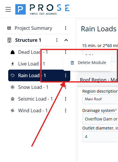
Module Management
Deleting the Rain Load Module
Remove the entire Rain Load module from your project when it's no longer needed.
- Hover over Rain Load - 1 in the left sidebar
- Click the three-dot menu icon that appears
- Select Delete Module from the dropdown menu
- Confirm the deletion when prompted
Permanent Deletion
Deleting the Rain Load module removes all roof regions, drainage configurations, and design loads. Export your data to PDF before deletion if you need to preserve this information.
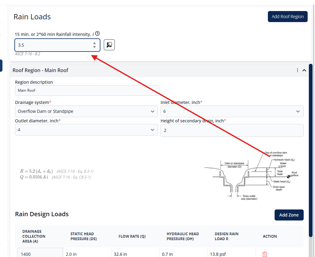
Rainfall Intensity
The rainfall intensity input is the foundation of rain load calculations. Per ASCE 7-16 Section 8.2, the module requires either the 15-minute or 2 times the 60-minute rainfall intensity in inches per hour.
Setting Rainfall Intensity
- Enter the rainfall intensity value in the input field (minimum 0.001 in/hr)
- The value represents the design rainfall intensity for your project location
- Click See Rain fall intensity maps to access interactive maps
- The ASCE 7-16 Section 8.2 reference is displayed next to the input
Changes to rainfall intensity automatically recalculate flow rates and design loads for all roof regions and drainage zones.
Interactive Rainfall Maps
The interactive map viewer provides access to ASCE 7-16 rainfall intensity maps directly within the application. Use the navigation controls to pan and zoom to your project location and read the rainfall intensity contours.
Roof Regions
Roof regions represent distinct areas of a roof with independent drainage systems. Each roof region can contain multiple drainage zones and is configured with a specific drainage system type.
Adding Roof Regions
- Click the Add Roof Region button at the top of the page
- A new roof region panel will be created with default parameters
- Enter a descriptive name in the "Region description" field
- Configure the drainage system parameters
- Add drainage zones to the region
The new roof region appears as a collapsible panel below existing regions, defaulting to "Overflow Dam or Standpipe" drainage system.
Editing Roof Regions
Modify roof region settings at any time:
- Click on the roof region header to expand the panel
- Update the region description in the name field
- Modify drainage system type or parameters as needed
- Changes are saved automatically
When expanded, the roof region displays the region description, drainage system configuration, ASCE 7 equations with diagram, and the design loads table.
Deleting Roof Regions
Remove roof regions that are no longer needed:
- Expand the roof region panel by clicking the header
- Click the Delete Region button
- Confirm the deletion when prompted
Cascading Deletion
Deleting a roof region removes all drainage zones within it. Export your data to PDF before deletion if you need to preserve this information.
Drainage Systems
The module supports four drainage system types based on ASCE 7-16 guidance. Each system type has specific parameters that affect the hydraulic head pressure calculation.
Drainage System Types
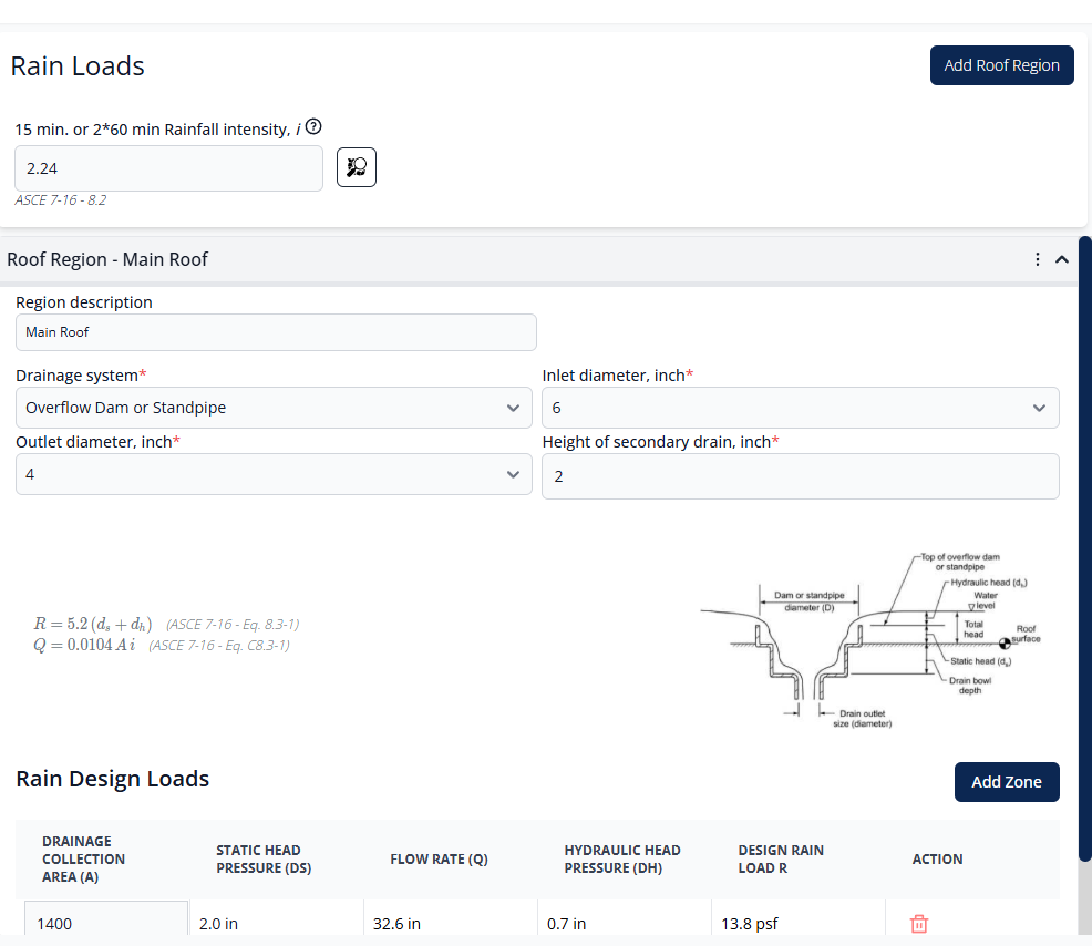
Overflow Dam or Standpipe
A drainage system where water ponds to a specific height before overflowing through a dam or standpipe. This is the simplest drainage system configuration with primary and secondary drain height differential.
Boxed (Closed) Scupper
An enclosed scupper system where water flows through a box-shaped opening. The hydraulic behavior is influenced by the inlet and outlet dimensions and the pressure head.
Channel Scupper
An open channel scupper system where water flows over a weir or through an open channel. Flow characteristics differ from closed scuppers due to free surface flow.
Circular Scuppers
Circular pipe scupper outlets. The hydraulic analysis accounts for circular cross-section flow characteristics and pipe friction.
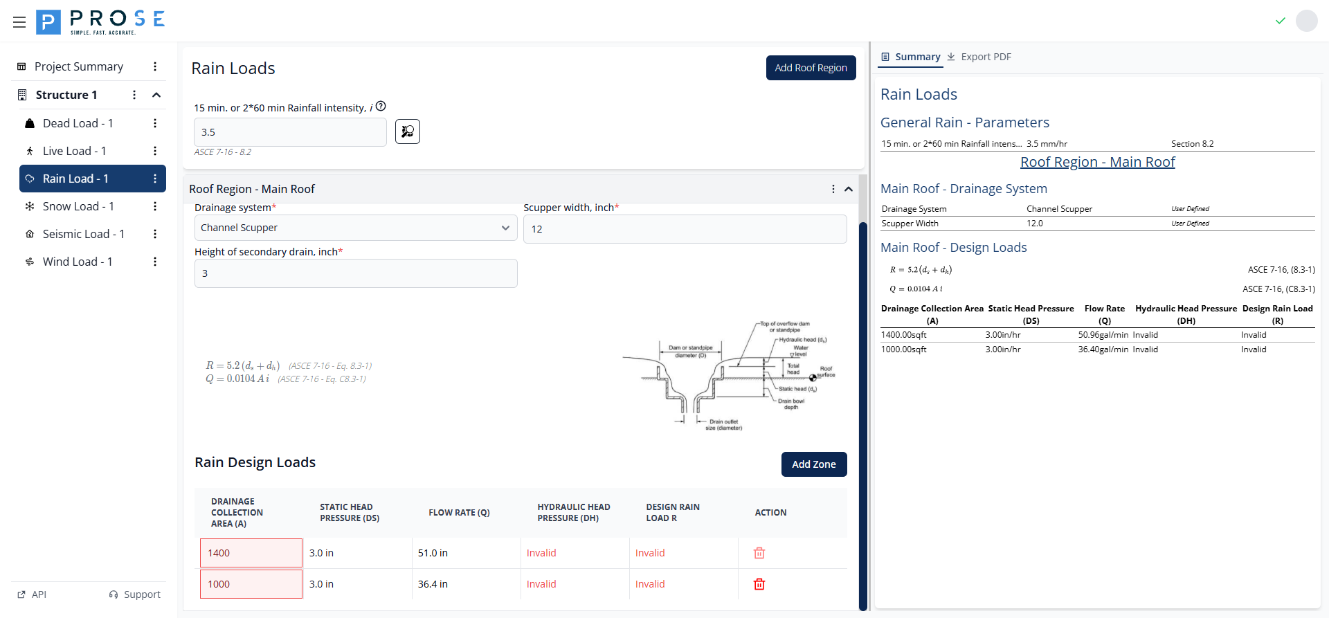
Drainage System Parameters
Configure the following parameters for each drainage system:
- Drainage system: Select from the four drainage system types (required)
- Inlet diameter, inch: Diameter of the drainage inlet opening (options: 6", 8", 12.75", 17")
- Outlet diameter, inch: Diameter of the drainage outlet (4" default)
- Scupper width, inch: For channel scuppers, width of the channel opening (6-24 inches)
- Height of secondary drain, inch: Elevation difference between primary and secondary drainage (minimum 0")
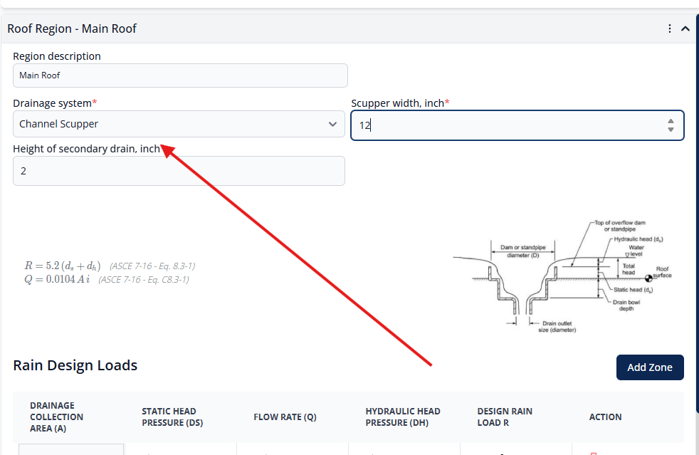
When you change the drainage system type, the parameter fields update to show only the relevant inputs for that system type.
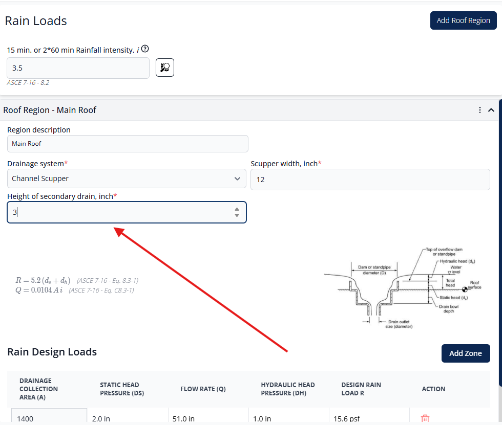
The height of the secondary drain is critical as it directly determines the static head pressure (ds) component in the rain load equation.
ASCE 7-16 Equations
The module uses the following governing equations:
Design rain load equation where R is in psf
Flow rate equation where Q is in gal/min, A is in sqft, and i is in in/hr
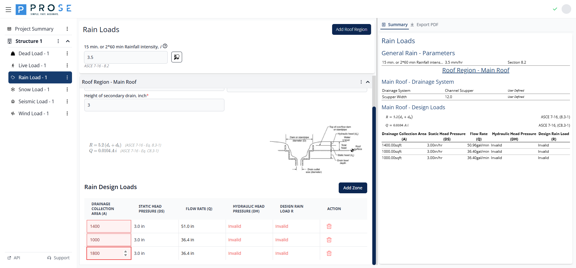
Drainage Zones
Drainage zones represent individual drainage collection areas within a roof region. Each zone has its own drainage collection area and calculated design loads.
Adding Drainage Zones
- Expand a roof region panel to view its drainage zones
- Click the Add Zone button
- A new drainage zone row appears in the design loads table
- Enter the drainage collection area in square feet
- Design loads are calculated automatically
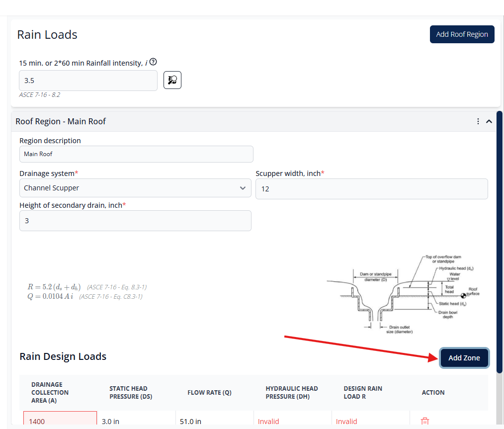
Each new zone is added as a row in the design loads table with editable drainage collection area and auto-calculated design parameters.
Editing Drainage Zones
Modify the drainage collection area for any zone to update its design loads:
- Click in the drainage collection area field
- Enter the new area value in square feet
- All calculated values update immediately
- Flow rate, hydraulic head, and design rain load recalculate based on the new area
Deleting Drainage Zones
Remove individual drainage zones that are no longer needed:
- Locate the zone row in the design loads table
- Click the Delete Load button in the Action column
- The zone is removed immediately
- Remaining zones are unaffected
Zone Design Load Calculations
The module calculates five key values for each drainage zone:
| Parameter | Description | Units |
|---|---|---|
| Drainage Collection Area (A) | User-input area that drains to this location | sqft |
| Static Head Pressure (ds) | Pressure due to static water depth | inches |
| Flow Rate (Q) | Calculated drainage flow rate | gal/min |
| Hydraulic Head Pressure (dh) | Additional pressure due to flow resistance | inches |
| Design Rain Load (R) | Final design rain load per Eq. 8.3-1 | psf |
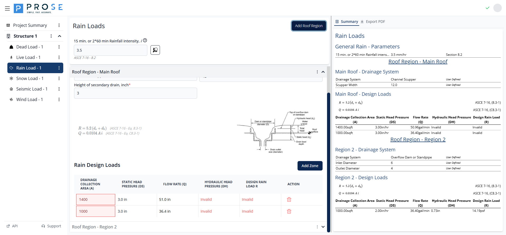
Design Loads Table
The design loads table displays all drainage zones for a roof region with real-time calculated values. The table updates automatically when you modify drainage collection areas or drainage system parameters.
Real-Time Calculations
All calculated values update immediately when you modify:
- Drainage collection area for any zone
- Rainfall intensity
- Drainage system parameters (inlet diameter, outlet diameter, secondary drain height)
- Drainage system type
This real-time feedback allows engineers to quickly evaluate different drainage configurations and optimize the design for minimal rain loads while ensuring adequate drainage capacity.
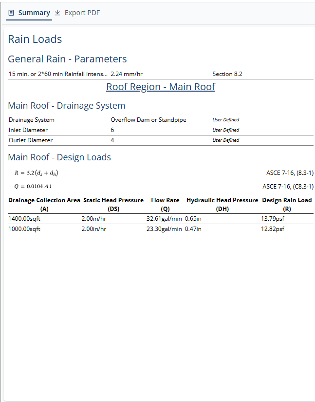
Summary View
The Summary tab provides a comprehensive overview of all rain load parameters and calculations for documentation and review purposes.
Summary Sections
General Rain Parameters
- 15 min. or 2*60 min Rainfall intensity with value and units
- ASCE 7 Section 8.2 reference
Roof Region Details
For each roof region, the summary displays:
- Drainage System: Selected system type
- Inlet Diameter: Configured inlet size in inches
- Outlet Diameter: Configured outlet size in inches
Design Loads
Complete table of all drainage zones with ASCE 7-16 equation references and all calculated values.
PDF Export
Generate professional documentation of your rain load calculations for project deliverables.
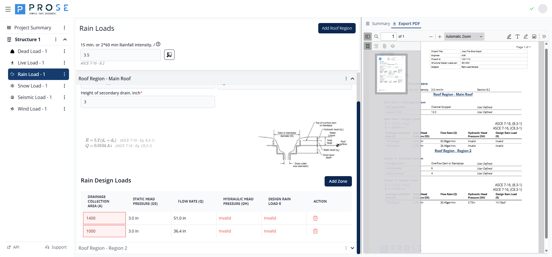
PDF Contents
- Project Header: Includes project title, engineer, ID, and design code
- Company Branding: Prose Engineering logo and contact information
- General Rain Parameters: Rainfall intensity with ASCE 7 Section reference
- Roof Region Details: All configured roof regions with drainage system specifications
- Design Loads Table: Complete calculations for all drainage zones
- ASCE 7-16 Equation References: Equations 8.3-1 and C8.3-1 displayed in tables
Generating PDFs
- Click the Export PDF tab on the Rain Load page
- The PDF generates automatically in the embedded viewer
- Review all roof regions and design load calculations
- Use the viewer controls to zoom, navigate, or print
- Click the Save button in the PDF viewer toolbar to download the PDF
Best Practices
See Also
- For coordinating rain loads with other roof loads, see the Roof Design Workflow
- For rain-on-snow considerations, see the Snow Loads documentation
- For troubleshooting, see Rain Load Issues
Roof Region Organization
- Create separate roof regions for distinct drainage systems or roof areas
- Use clear, descriptive region names (e.g., "Main Roof", "Canopy", "Mechanical Penthouse")
- Group drainage zones by common drainage system characteristics
- Consider multiple regions for roofs with different slopes or drainage patterns
Drainage Zone Modeling
- Accurately measure drainage collection areas from roof plans
- Account for roof slope when calculating horizontal projected areas
- Consider multiple zones for large roofs to model distributed drainage
- Verify drainage areas sum to total roof area
- Model critical drainage points where ponding is most likely
Rainfall Intensity Selection
- Use interactive maps to accurately determine site-specific rainfall intensity
- Verify local amendments to ASCE 7-16 rainfall intensity values
- Consider using more conservative values for critical facilities
- Document the source and basis of rainfall intensity selection
Drainage System Configuration
- Coordinate drainage system type with architectural roof drainage design
- Verify inlet and outlet diameters match as-built or specified drainage hardware
- Set secondary drain height per code requirements (typically 2" minimum)
- Model actual drainage system geometry rather than using default values
Secondary Drainage
IBC requires secondary (emergency) drainage for all roofs. The height of secondary drain directly affects the static head (ds) in your rain load calculations.
Code Reference
The Rain Load module is based on ASCE 7-16 (Minimum Design Loads and Associated Criteria for Buildings and Other Structures):
Primary References
- Section 8.2: Rainfall Intensity - Specifies design rainfall intensity values
- Section 8.3: Design Rain Loads - Rain load calculation equation R = 5.2(ds + dh)
- Equation 8.3-1: Rain load on undeflected roof
- Equation C8.3-1: Flow rate calculation Q = 0.0104 A i
Related Code Sections
- Section 8.4: Ponding Instability - Requirements for ponding analysis
- IBC Section 1503.4: Roof drainage requirements and secondary drainage
- IPC Chapter 11: Plumbing code requirements for roof drainage sizing
Code Variables
The module uses standard ASCE 7-16 notation:
- R: Rain load on the undeflected roof (psf)
- ds: Depth of water on undeflected roof up to inlet of primary drainage (in)
- dh: Additional depth of water above inlet of primary drainage at design flow (in)
- Q: Flow rate through drainage system (gal/min)
- A: Drainage collection area (sqft)
- i: Rainfall intensity (in/hr)