Seismic Building Design
Seismic building design involves selecting appropriate structural systems and configurations that can resist earthquake forces while maintaining life safety and, depending on the performance objectives, limiting damage and maintaining functionality.
Key Features
- Multi-level building geometry with seismic weights
- Complete ASCE 7-16 Table 12.2-1 SFRS library
- Automatic R, Ω0, and Cd factor lookup
- Height limit verification by Seismic Design Category
- Approximate fundamental period calculation
- Base shear calculation with code-prescribed limits
- Vertical force distribution (Fx and Cvx)
- Diaphragm design forces (Fpx)
- Multiple SFRS support for orthogonal directions
- Professional PDF export with code references
Seismic Force-Resisting Systems (SFRS)
Common SFRS Types
ASCE 7 Table 12.2-1 lists approved seismic force-resisting systems:
Moment Frame Systems
- Special Moment Frames (SMF): Highest ductility, R = 8 (steel), R = 8 (concrete)
- Intermediate Moment Frames (IMF): Moderate ductility, R = 4.5 (steel), R = 5 (concrete)
- Ordinary Moment Frames (OMF): Limited ductility, R = 3.5 (steel), R = 3 (concrete)
Braced Frame Systems
- Special Concentrically Braced Frames (SCBF): High ductility, R = 6 (steel)
- Buckling-Restrained Braced Frames (BRBF): Enhanced ductility, R = 8 (steel)
- Eccentrically Braced Frames (EBF): High ductility through shear links, R = 8 (steel)
- Ordinary Concentrically Braced Frames (OCBF): Limited ductility, R = 3.25
Shear Wall Systems
- Special Reinforced Concrete Shear Walls: High ductility, R = 5 (bearing wall), R = 6 (building frame)
- Special Steel Plate Shear Walls: High ductility, R = 7
- Ordinary Reinforced Concrete Shear Walls: Limited ductility, R = 4 (bearing wall)
Dual Systems
- Special Moment Frame + SCBF or Shear Walls: R = 7-8 depending on configuration
- Moment frame must independently resist at least 25% of seismic forces
- Combines ductility of moment frame with stiffness of braced frame or shear wall
Response Modification Factors
SFRS Selection
Higher R values mean lower design forces but require more stringent detailing. Balance design force reduction against construction complexity and inspection requirements.
R Factor (Response Modification Coefficient)
The R factor accounts for the system's ability to dissipate energy through inelastic behavior:
- Higher R values (6-8): More ductile systems, lower design forces
- Lower R values (3-4): Less ductile systems, higher design forces
- Affects base shear calculation: V = CsW, where Cs is inversely proportional to R
Ω0 (Overstrength Factor)
Used for designing certain elements that must remain elastic:
- Column splices in moment frames
- Foundations
- Elements supporting discontinuous systems
- Typically ranges from 2 to 3
Cd (Deflection Amplification Factor)
Amplifies elastic deflections to estimate inelastic drift:
- Used for drift calculations and separation between buildings
- Typically ranges from 3 to 6
- δx = Cd δxe / Ie
Building Configuration
Structural Irregularities
ASCE 7 Section 12.3 defines horizontal and vertical irregularities that affect design:
Horizontal Irregularities
- Torsional Irregularity: Drift at one end exceeds 1.2 times average drift
- Re-entrant Corner: Plan projections beyond re-entrant corner exceed 15% of dimension
- Diaphragm Discontinuity: Openings exceed 50% of gross enclosed area
- Out-of-Plane Offsets: Discontinuities in lateral force path
- Nonparallel Systems: Vertical elements not parallel or symmetric
Vertical Irregularities
- Soft Story: Story stiffness less than 70% of story above or 80% of average
- Weight (Mass) Irregularity: Effective mass exceeds 150% of adjacent story
- Geometric Irregularity: Horizontal dimension exceeds 130% of adjacent story
- In-Plane Discontinuity: Offset of lateral force-resisting elements
- Weak Story: Story strength less than 80% of story above
Impact of Irregularities
Irregularities may trigger:
- Prohibition of certain analysis procedures
- Reduced R factors
- More stringent detailing requirements
- Additional design checks
Design Philosophy
Performance Objectives
Modern seismic design aims to provide:
- Frequent Earthquakes (43-year return): Essentially elastic response, no damage
- Occasional Earthquakes (72-year return): Minor repairable damage
- Design Earthquake (475-year return): Moderate damage, life safety maintained
- Maximum Earthquake (2,475-year return): Significant damage, but no collapse
Capacity Design Principles
Key concepts in seismic design:
- Strong Column-Weak Beam: Ensure columns remain elastic while beams yield
- Ductile Fuse Elements: Concentrate inelastic behavior in designated elements
- Redundancy: Multiple load paths prevent progressive collapse
- Regular Configuration: Avoid irregularities that concentrate demands
Diaphragm Design
Diaphragm Classification
Per ASCE 7 Section 12.3.1:
- Rigid Diaphragms: Distribute lateral forces based on relative stiffness of vertical elements
- Flexible Diaphragms: Distribute lateral forces as simple span elements
- Semi-rigid Diaphragms: Require explicit modeling of diaphragm flexibility
Diaphragm Forces
Design forces for diaphragms:
Where:
- Fpx: Diaphragm design force
- wpx: Weight tributary to the diaphragm
- Σ Fi: Sum of design forces at and above the level
- Σ wi: Sum of weights at and above the level
Collector Elements and Load Path
Collectors (Drag Struts)
Elements that collect diaphragm forces and transfer them to vertical elements:
- Required where vertical elements don't align with edges of diaphragm openings
- Must be designed for forces amplified by overstrength factor Ω0
- Critical for diaphragm openings and discontinuities
Load Path Continuity
Ensure complete load path from point of application to foundation:
- Positive connections at all interfaces
- Special detailing at discontinuities
- Foundation-to-superstructure connections
- Consideration of vertical earthquake effects
Getting Started
- Complete the Seismic Design Criteria tab first
- Click the Seismic Building Design tab
- Add building levels with elevations and seismic weights
- Select the appropriate SFRS category and system
- Review base shear and force distribution calculations
- Add additional systems for orthogonal directions if needed
- Review the Summary tab and export to PDF
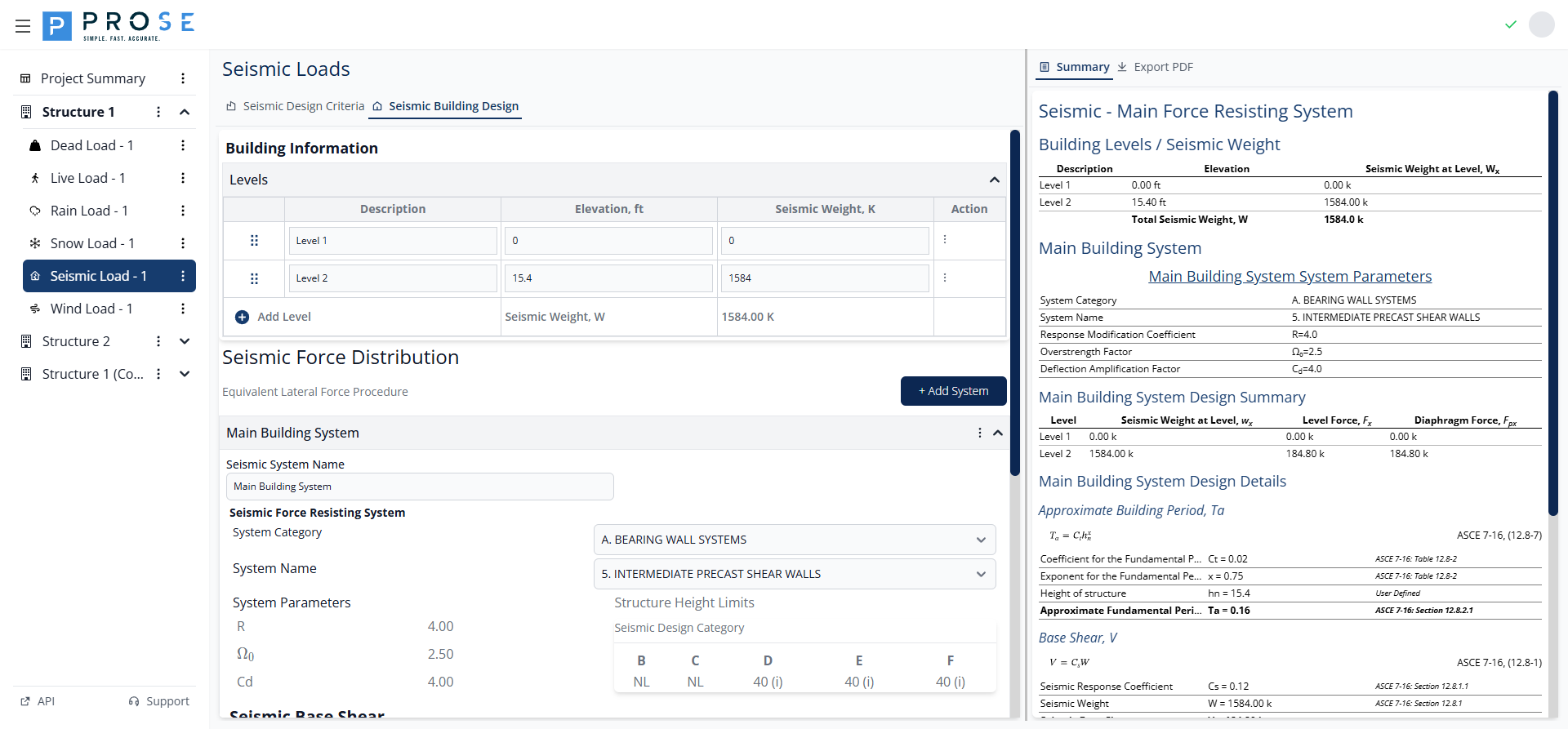
Building Level Management
The Building Information section allows you to define the building geometry and seismic weights at each level.
Adding Building Levels
- Click the Add Level button
- Enter a description for the level (e.g., "Level 1", "Roof", "Penthouse")
- Enter the elevation above base in feet
- Enter the seismic weight at the level in kips
- The total seismic weight (W) updates automatically
Editing Building Levels
- Click in any field to modify the value
- Update the description, elevation, or seismic weight as needed
- Changes are saved automatically
- Use the drag handle (⋮⋮) to reorder levels
Deleting Building Levels
- Click the trash icon in the Action column
- The level is removed immediately
- Force distribution recalculates automatically
Levels Table Reference
| Column | Description |
|---|---|
| Description | Level name (e.g., "Level 1", "Roof", "Penthouse") |
| Elevation, ft | Height above base to the level |
| Seismic Weight, K | Effective seismic weight at the level in kips |
| Action | Delete button to remove the level |
SFRS Selection
The Seismic Force Distribution section allows you to define the seismic force-resisting system:

System Category Selection
Click the System Category dropdown to select from ASCE 7-16 Table 12.2-1 categories:
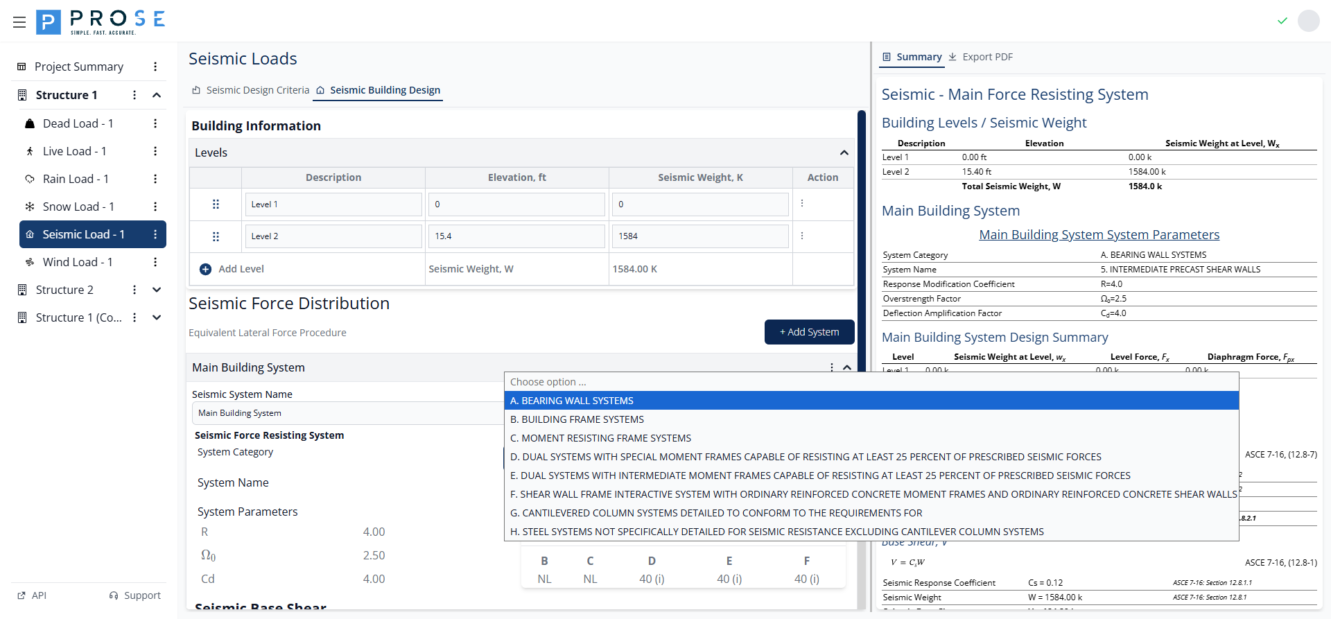
| Category | Description |
|---|---|
| A | Bearing Wall Systems |
| B | Building Frame Systems |
| C | Moment Resisting Frame Systems |
| D | Dual Systems with Special Moment Frames |
| E | Dual Systems with Intermediate Moment Frames |
| F | Shear Wall Frame Interactive System |
| G | Cantilevered Column Systems |
| H | Steel Systems Not Specifically Detailed |
System Name Selection
After selecting a category, choose the specific system type from the System Name dropdown. The available options depend on the selected category.
System Parameters
Prose automatically displays system parameters from ASCE 7-16 Table 12.2-1:
| Parameter | Description |
|---|---|
| R | Response Modification Coefficient |
| Ω0 | Overstrength Factor |
| Cd | Deflection Amplification Factor |
Structure Height Limits
The height limits table shows allowable building heights by Seismic Design Category (SDC):
- NL: No Limit
- NP: Not Permitted
- Numeric values: Maximum height in feet
- (i), (j), etc.: Special footnote conditions
Adding Multiple Systems
For buildings with different systems in orthogonal directions:
- Click + Add System button
- Enter a descriptive name for the new system
- Select the appropriate System Category and System Name
- Each system is calculated independently
Base Shear Calculations
The Seismic Base Shear section displays the complete base shear calculation:

Approximate Fundamental Period (Ta)
Per ASCE 7-16 Equation 12.8-7:
| Parameter | Description | Source |
|---|---|---|
| Ct | Period coefficient | ASCE 7-16 Section 12.8.2.1 |
| hn | Structure height (ft) | User Defined |
| x | Period exponent | ASCE 7-16 Section 12.8.2.1 |
| Ta | Approximate period (sec) | Calculated |
Base Shear (V)
Per ASCE 7-16 Equation 12.8-1:
| Parameter | Description | Source |
|---|---|---|
| Cs | Seismic response coefficient | ASCE 7-16 Section 12.8.1.1 |
| W | Effective seismic weight (kips) | ASCE 7-16 Section 12.8.1 |
| V | Seismic base shear (kips) | Calculated |
Force Distribution
The Distribution of Forces table shows the vertical distribution of seismic loads:

| Column | Description | Reference |
|---|---|---|
| Name | Level description | - |
| Elevation | Height above base | - |
| Weight | Seismic weight at level | - |
| Cvx | Vertical distribution factor | ASCE 7-16 Eq. 12.8-12 |
| Fx | Lateral force at level | ASCE 7-16 Eq. 12.8-11 |
| Fpx | Diaphragm design force | ASCE 7-16 Eq. 12.10-1 |
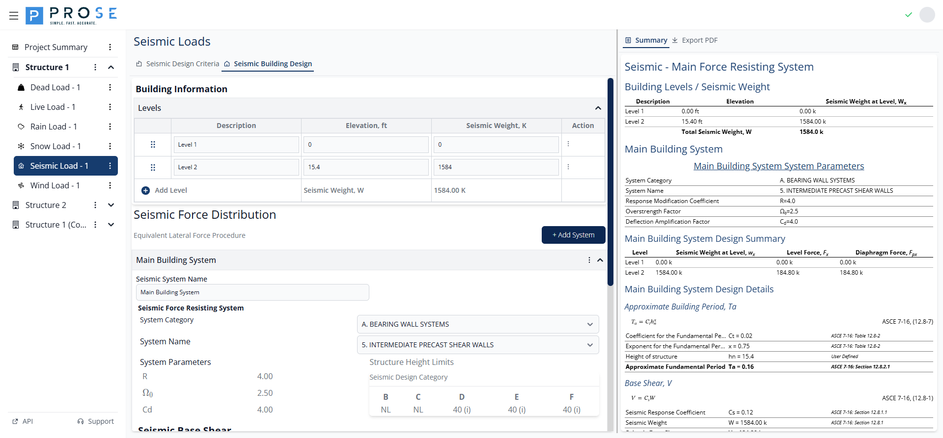
Summary View
Click the Summary tab to view a comprehensive report of all seismic building design calculations:

The summary includes:
- Building Levels / Seismic Weight table
- System Parameters (R, Ω0, Cd)
- Design Summary with level forces
- Design Details with complete calculations
- Vertical Distribution tables for Fx and Fpx
PDF Export
Generate professional documentation of your seismic building design for project deliverables.
Generating PDFs
- Click the Export PDF tab
- Review the generated PDF in the embedded viewer
- Use viewer controls to zoom or navigate
- Click Save to download
PDF Contents
- Project header with title, engineer, ID, and design code
- Company branding
- Building level geometry and seismic weights
- SFRS parameters with code references
- Base shear calculations
- Force distribution tables
- Diaphragm design forces
Best Practices
See Also
- Ensure Design Criteria are complete before configuring building design
- For comparing seismic vs wind base shear, see Lateral Force Analysis
- For troubleshooting base shear issues, see Seismic Load Issues
- Select SFRS with highest practical R factor to reduce design forces
- Strive for regular, symmetric building configuration
- Avoid soft stories and other severe irregularities
- Provide redundancy with multiple bays of lateral resistance
- Detail connections for ductility and load path continuity
- Coordinate architectural and structural layouts early in design
- Consider constructability and inspection requirements for chosen SFRS
Code Reference
Seismic building design per ASCE 7-16:
- Chapter 12: Seismic Design Requirements for Building Structures
- Section 12.8: Equivalent Lateral Force Procedure
- Section 12.8.1: Seismic Base Shear
- Section 12.8.2: Period Determination
- Section 12.8.3: Vertical Distribution of Seismic Forces
- Section 12.10: Diaphragm Design Forces
- Table 12.2-1: Design Coefficients and Factors for SFRS
- Section 12.3: Structural Irregularities