Seismic Design Criteria
Seismic design criteria establish the basis for calculating earthquake forces and selecting appropriate design procedures. These criteria are determined from site-specific seismic hazard parameters and building characteristics.

Key Features
- Mapped spectral acceleration lookup (SS and S1) per ASCE 7-16 Chapter 22
- Automatic site coefficient calculation (Fa and Fv) based on site class
- MCER and design spectral acceleration calculations
- Seismic Design Category (SDC) determination per Tables 11.6-1 and 11.6-2
- Interactive design response spectrum visualization
- Integration with Building Design module for force distribution
- Professional PDF export with code references
Site Class Determination
Site Classification (ASCE 7 Section 20.3)
Site class is based on soil properties in the upper 100 feet:
| Site Class | Description | Average Shear Wave Velocity |
|---|---|---|
| A | Hard Rock | > 5,000 ft/s |
| B | Rock | 2,500 to 5,000 ft/s |
| C | Very Dense Soil/Soft Rock | 1,200 to 2,500 ft/s |
| D | Stiff Soil (Default) | 600 to 1,200 ft/s |
| E | Soft Clay Soil | < 600 ft/s |
| F | Special Study Required | - |
Default Site Class
When geotechnical data is not available:
- Site Class D: Used as default for most locations
- Site Class C: May be used in some jurisdictions with documented hard site conditions
- Site-Specific Investigation: Required for Site Class E or F, or when S1 >= 0.2
Site Class F
Site Class F requires a site-specific ground motion hazard analysis. The module cannot calculate site coefficients for Site Class F—consult a geotechnical engineer.
Seismic Ground Motion Parameters
Mapped Spectral Acceleration Values
Obtained from ASCE 7 Chapter 22 maps or online tools:
- SS: Mapped spectral acceleration at short periods (0.2 second)
- S1: Mapped spectral acceleration at 1-second period
Site Coefficients
Adjust mapped values based on site class:
- Fa: Short-period site coefficient (from ASCE 7 Table 11.4-1)
- Fv: Long-period site coefficient (from ASCE 7 Table 11.4-2)
Maximum Considered Earthquake (MCER) Response
Site-adjusted spectral acceleration parameters:
Design Spectral Acceleration Parameters
Design values are ⅔ of MCER values:
Seismic Design Category (SDC)
Determining SDC
SDC is determined from ASCE 7 Tables 11.6-1 and 11.6-2 based on:
- Design spectral acceleration (SDS and SD1)
- Risk Category (I, II, III, or IV)
Seismic Design Categories
| SDC | Seismic Hazard | Design Requirements |
|---|---|---|
| A | Very Low | Minimal seismic requirements, wind may govern |
| B | Low | Basic seismic detailing |
| C | Moderate | Intermediate seismic detailing, limited system choices |
| D | High | Strict requirements, special systems required |
| E | Very High | Most stringent requirements |
| F | Extreme (near fault) | Special studies, enhanced detailing |
SDC Impact on Design
Higher SDC imposes more stringent requirements:
- SDC A-B: Basic structural integrity, limited seismic provisions
- SDC C: Intermediate detailing, restrictions on certain systems and irregularities
- SDC D-F: Special seismic systems required, strict irregularity limitations, enhanced detailing
Risk Category and Importance Factor
Risk Categories (ASCE 7 Table 1.5-1)
| Risk Category | Buildings | Ie |
|---|---|---|
| I | Agricultural facilities, minor storage | 1.0 |
| II | Standard occupancy (residential, office, retail) | 1.0 |
| III | Substantial public assembly, schools, jails | 1.25 |
| IV | Essential facilities (hospitals, fire stations, emergency operations) | 1.5 |
Seismic Importance Factor (Ie)
Used in base shear calculation and drift limits:
- Increases design forces for more critical facilities
- Tightens drift limits for essential and high-occupancy buildings
- Applied directly to seismic response coefficient
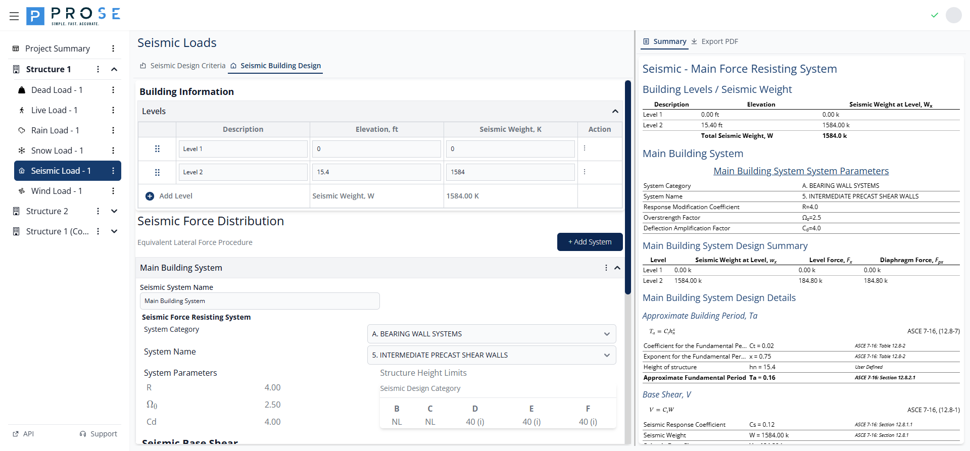
Seismic Base Shear
Equivalent Lateral Force Procedure
The seismic base shear V is calculated as:
Seismic Response Coefficient (Cs)
General equation:
With upper and lower bounds:
- Maximum: Cs shall not exceed SD1 / [T(R / Ie)]
- Minimum (S1 >= 0.6g): Cs >= 0.5 S1 / (R / Ie)
- Minimum (all other): Cs >= 0.044 SDS Ie >= 0.01
Effective Seismic Weight (W)
Total effective seismic weight includes:
- Total dead load
- Applicable portions of other loads (per ASCE 7 Section 12.7.2):
- 25% of floor live load in storage areas
- Minimum of 10 psf partition load where used
- Total weight of permanent equipment
- 20% of flat roof snow load where pf > 30 psf
Fundamental Period (T)
Approximate Period (Ta)
Per ASCE 7 Section 12.8.2.1:
Where:
- hn: Height above base to highest level (feet)
- Ct and x: Building type coefficients
- Steel moment frames: Ct = 0.028, x = 0.8
- Concrete moment frames: Ct = 0.016, x = 0.9
- Steel eccentrically braced frames: Ct = 0.03, x = 0.75
- All other systems: Ct = 0.02, x = 0.75
Computed Period Limitations
If using computer analysis period T:
- T shall not exceed: Cu Ta
- Cu: Coefficient for upper limit (from ASCE 7 Table 12.8-1), typically 1.4 to 1.7
- Prevents underestimation of base shear from overly flexible models
Vertical Distribution of Seismic Forces
Lateral Force at Level x
Vertical Distribution Factor
Where:
- wx: Portion of W at level x
- hx: Height from base to level x
- k: Exponent related to period
- k = 1.0 for T <= 0.5 seconds
- k = 2.0 for T >= 2.5 seconds
- Linear interpolation between 0.5 and 2.5 seconds
Drift Limits
Story Drift Calculation
Design story drift:
Where:
- δxe: Elastic deflection from seismic forces
- Cd: Deflection amplification factor
- Ie: Seismic importance factor
Allowable Story Drift (Δa)
| Structure Type | Risk Category I or II | Risk Category III or IV |
|---|---|---|
| Buildings, 4 stories or less with systems designed to accommodate drift | 0.025hsx | 0.020hsx |
| Other buildings with moment-resisting frames | 0.020hsx | 0.015hsx |
| Other buildings (shear walls, braced frames) | 0.020hsx | 0.015hsx |
Where hsx is the story height below level x.
Getting Started
- Navigate to your structure in the left sidebar
- Click the three-dot menu and select Add Module
- Choose Seismic Load from the module list
- The Seismic Design Criteria tab opens automatically
- Enter mapped spectral accelerations (SS and S1) from ASCE 7 maps
- Select the Site Class based on geotechnical data
- Review calculated design parameters and SDC
- Proceed to Building Design tab for force distribution
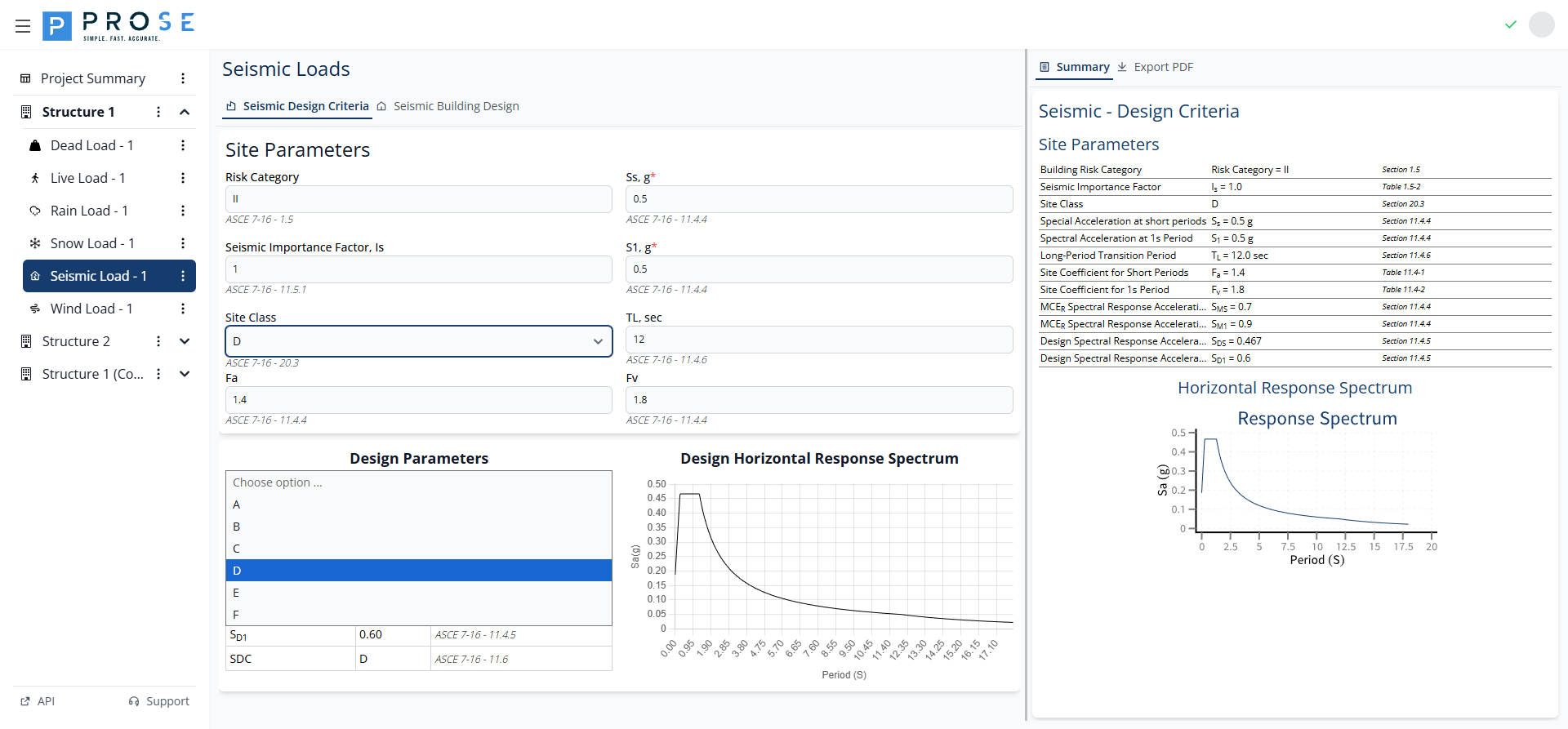
Site Parameters
The Site Parameters section contains all inputs required for seismic design criteria:
Input Fields
| Field | Description | Source |
|---|---|---|
| Risk Category | Building risk category (inherited from structure) | ASCE 7-16 Section 1.5 |
| Ss, g | Mapped spectral acceleration at short periods | ASCE 7-16 Section 11.4.4 |
| Seismic Importance Factor Is | Automatically calculated from Risk Category | ASCE 7-16 Section 11.5.1 |
| S1, g | Mapped spectral acceleration at 1-second period | ASCE 7-16 Section 11.4.4 |
| Site Class | Soil classification (A through F) | ASCE 7-16 Section 20.3 |
| TL, sec | Long-period transition period | ASCE 7-16 Section 11.4.6 |
| Fa | Short-period site coefficient (calculated) | ASCE 7-16 Section 11.4.4 |
| Fv | Long-period site coefficient (calculated) | ASCE 7-16 Section 11.4.4 |
Site Class Selection
Click the Site Class dropdown to select the appropriate soil classification:
| Site Class | Description |
|---|---|
| A | Hard Rock |
| B | Rock |
| C | Very Dense Soil and Soft Rock |
| D | Stiff Soil (Default) |
| E | Soft Clay Soil |
| F | Soils Requiring Site Response Analysis |
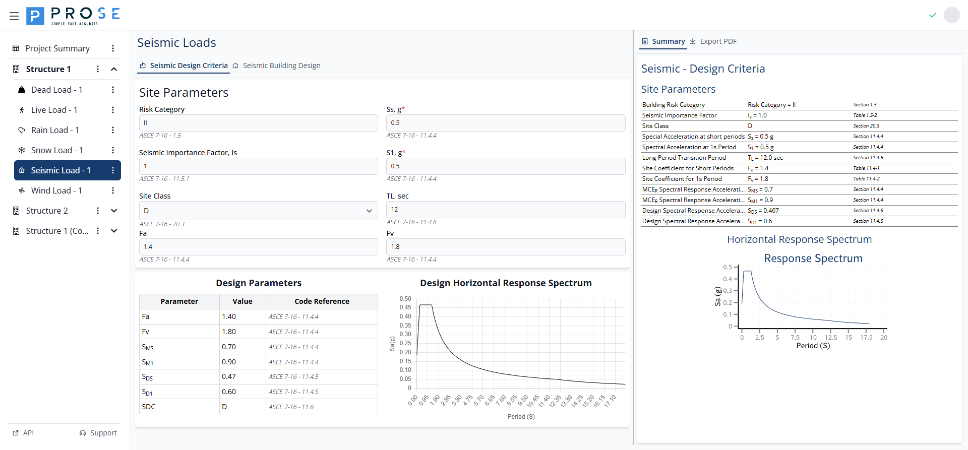
Design Parameters
The Design Parameters table displays all calculated values with ASCE 7-16 code references:

| Parameter | Description | Code Reference |
|---|---|---|
| Fa | Site coefficient for short periods | ASCE 7-16 Table 11.4-1 |
| Fv | Site coefficient for 1-second period | ASCE 7-16 Table 11.4-2 |
| SMS | MCER spectral acceleration at short periods | ASCE 7-16 Eq. 11.4-1 |
| SM1 | MCER spectral acceleration at 1-second period | ASCE 7-16 Eq. 11.4-2 |
| SDS | Design spectral acceleration at short periods | ASCE 7-16 Eq. 11.4-3 |
| SD1 | Design spectral acceleration at 1-second period | ASCE 7-16 Eq. 11.4-4 |
| SDC | Seismic Design Category | ASCE 7-16 Section 11.6 |
Response Spectrum
The response spectrum chart visualizes the design spectral acceleration across all periods, showing the characteristic shape with constant acceleration, constant velocity, and constant displacement regions:
Summary View
Click the Summary tab to view a comprehensive formatted report of all design criteria:
The summary includes:
- Building Risk Category and Importance Factor
- Site Class and spectral acceleration parameters
- Site coefficients (Fa and Fv)
- MCER spectral response accelerations
- Design spectral response accelerations
- Seismic Design Category determination
PDF Export
Generate professional documentation of your seismic design criteria for project deliverables.
Generating PDFs
- Click the Export PDF tab
- Review the generated PDF in the embedded viewer
- Use viewer controls to zoom or navigate
- Click Save to download
PDF Contents
- Project header with title, engineer, ID, and design code
- Company branding
- Site parameters with code references
- Design parameter calculations
- Response spectrum chart
- Seismic Design Category determination
Best Practices
See Also
- Complete your design criteria before proceeding to Building Design
- For lateral force comparison with wind, see Lateral Force Analysis
- For troubleshooting SDC issues, see Seismic Load Issues
- Always obtain geotechnical report for Site Class determination
- Use latest ASCE 7 maps; parameters are updated periodically
- Verify local amendments to national code requirements
- Document all assumptions in design criteria
- Consider site-specific ground motion analysis for critical facilities
- Check drift limits early in design; often controls member sizes
- Coordinate with peer reviewers on SDC and SFRS selection
Code Reference
Seismic design criteria per ASCE 7-16:
- Chapter 11: Seismic Design Criteria
- Section 11.4: Seismic Ground Motion Values
- Section 11.4.4: Design Spectral Acceleration Parameters
- Section 11.5: Importance Factor and Risk Category
- Section 11.6: Seismic Design Category
- Section 20.3: Site Classification
- Tables 11.4-1, 11.4-2: Site Coefficients Fa and Fv
- Tables 11.6-1, 11.6-2: Seismic Design Category Determination