Wind Loads
The Wind Load module provides comprehensive wind pressure calculations per ASCE 7-10 and ASCE 7-16 for structural design. The module supports Main Wind Force Resisting System (MWFRS) Directional Procedure and Components & Cladding (C&C) analysis with real-time calculations and professional PDF export.
Key Features
- Support for ASCE 7-10 and ASCE 7-16 code years (ASCE 7-22 in development)
- MWFRS Directional Procedure for all building heights (Chapter 27)
- Components & Cladding analysis for walls, roofs, and parapets (Chapter 30)
- Separate exposure categories for each cardinal direction
- Topographic factor calculations with multiple feature types
- Ground elevation factor for high-altitude sites
- Flexible and rigid building classification
- Multiple enclosure classifications with automatic GCpi calculation
- Real-time design pressure calculations
- Professional PDF export with project branding
Module Management
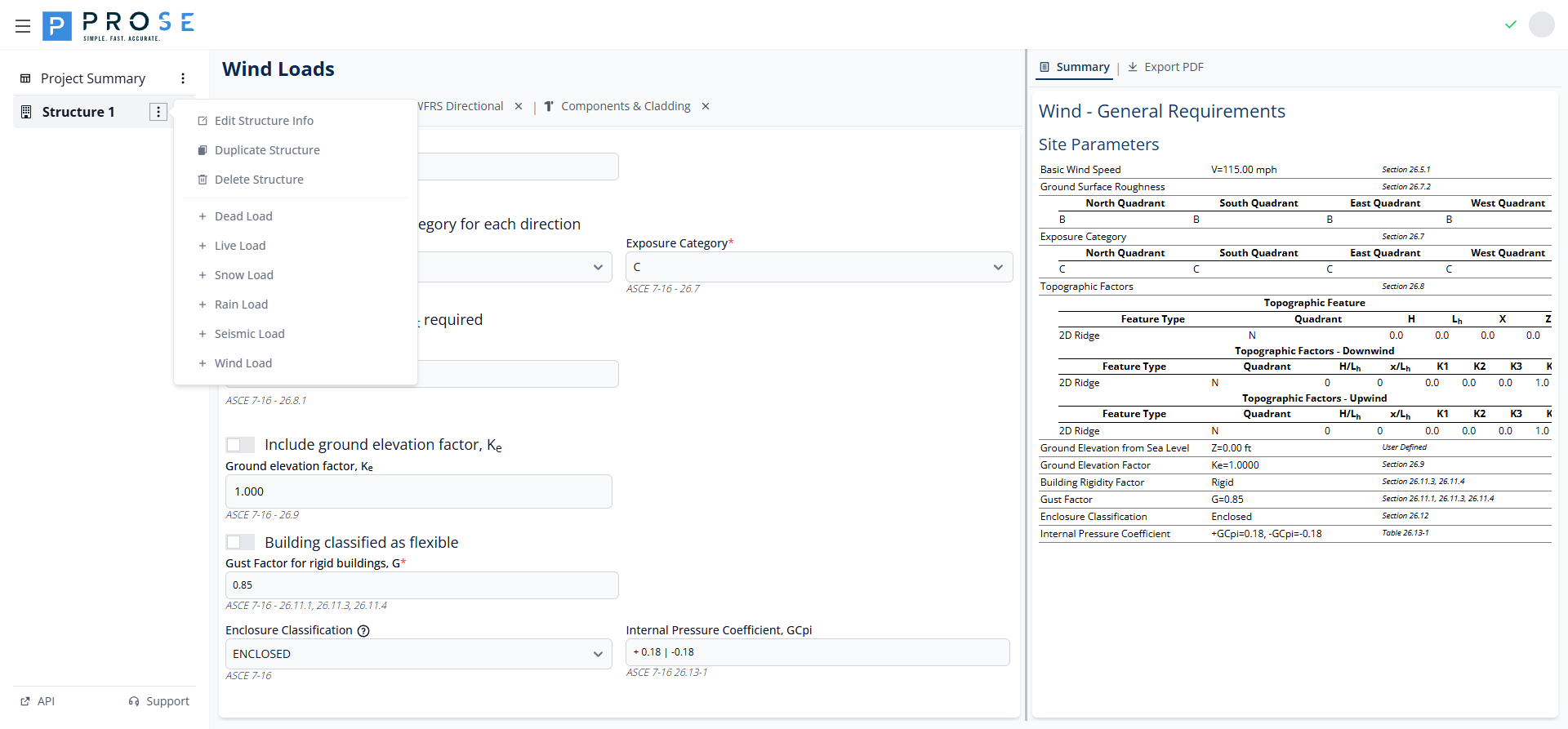
Adding the Wind Load Module
Add the Wind Load module to your project to begin wind pressure calculations.
- Click the Structure 1 button in the left sidebar
- Click the three-dot menu icon that appears
- Select Add Module from the dropdown menu
- Choose Wind Load from the available modules
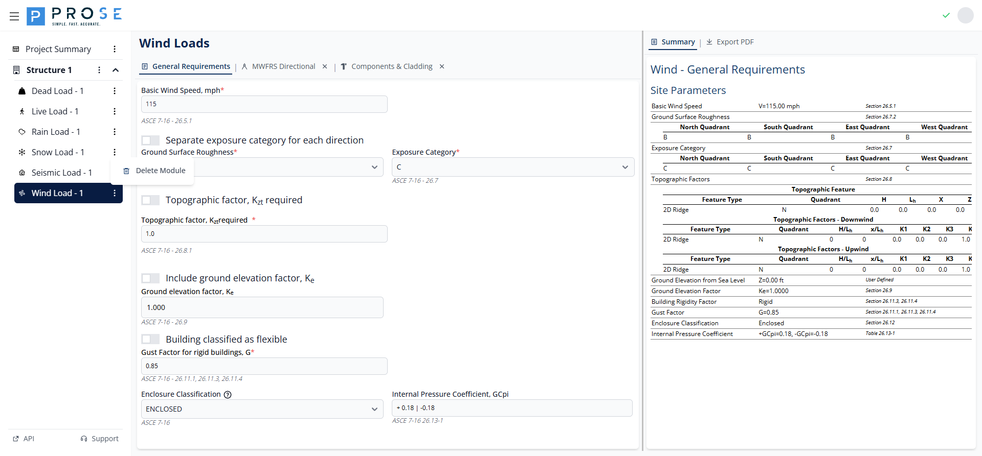
Deleting the Wind Load Module
Remove the entire Wind Load module from your project when it's no longer needed.
- Hover over Wind Load - 1 in the left sidebar
- Click the three-dot menu icon that appears
- Select Delete Module from the dropdown menu
- Confirm the deletion when prompted
Permanent Deletion
Deleting the Wind Load module removes all general requirements, MWFRS regions, C&C configurations, and design pressures. Export your data to PDF before deletion if you need to preserve this information.
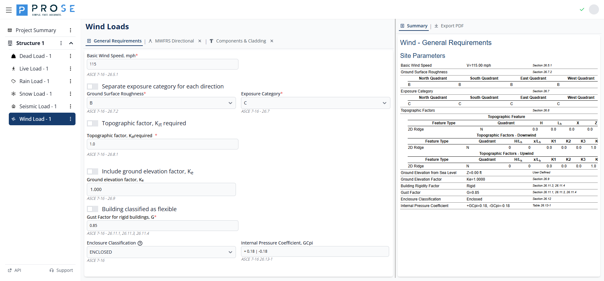
General Requirements
The General Requirements tab contains fundamental wind parameters that apply to all wind load calculations in the module. These parameters establish the baseline conditions for MWFRS and C&C analyses.

Basic Wind Speed
The basic wind speed is the fundamental input for all wind load calculations per ASCE 7-16 Section 26.5.1.
- Enter the basic wind speed value in mph
- The value represents the 3-second gust wind speed at 33 ft above ground
- Obtain values from ASCE 7 wind speed maps or local building codes
- Risk Category determines which wind speed map to use
Exposure Category
Exposure category accounts for the ground surface roughness affecting wind flow. The module supports consolidated or separate exposure categories per direction.
Consolidated Exposure
By default, a single exposure category applies to all wind directions:
- Exposure B: Urban and suburban areas with numerous closely spaced obstructions
- Exposure C: Open terrain with scattered obstructions, flat open country
- Exposure D: Flat, unobstructed areas exposed to wind flowing over open water
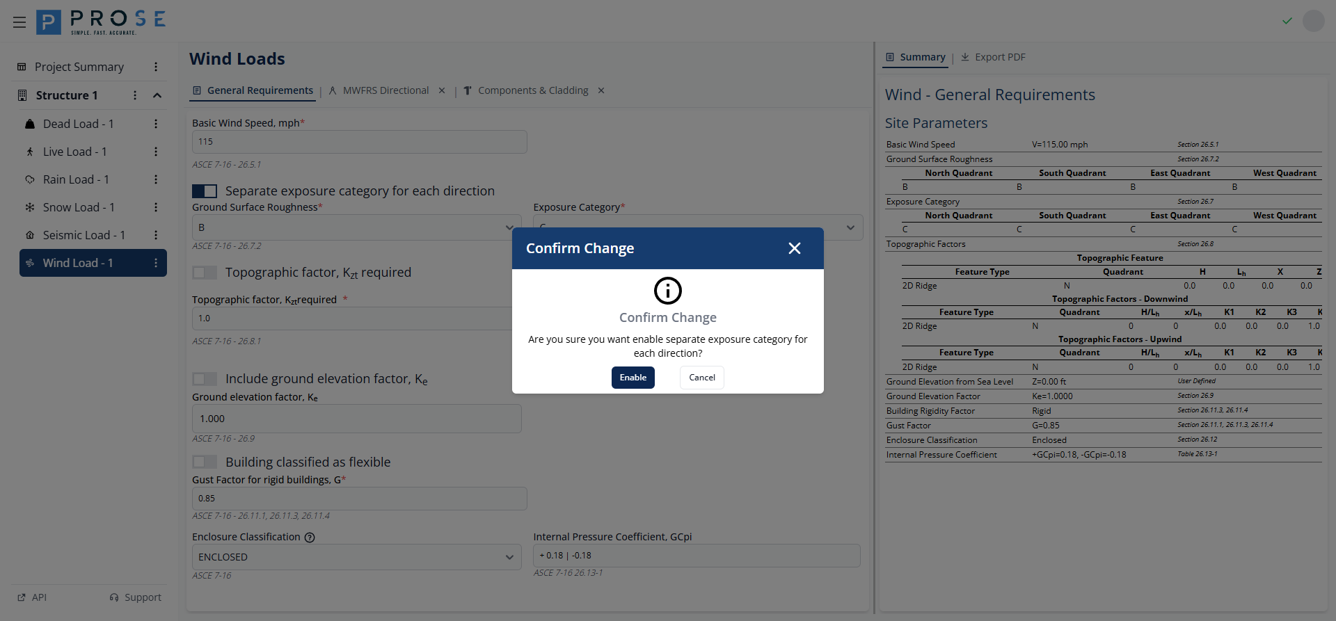
Separate Exposure by Direction
Enable direction-specific exposure categories when site conditions vary by cardinal direction.
- Check Separate exposure category for each direction
- A confirmation dialog appears explaining the implications
- Click Confirm to enable separate exposure
- Configure Ground Surface Roughness and Exposure Category for each direction (N, S, E, W)
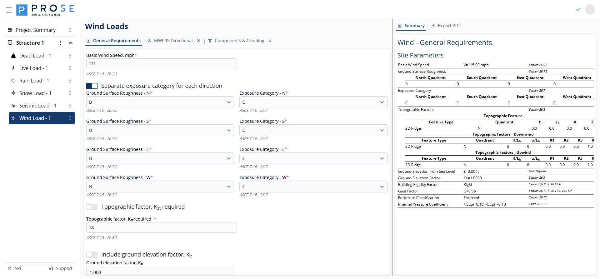
Ground Surface Roughness
Ground Surface Roughness (B, C, or D) per ASCE 7-16 Section 26.7.2 determines the Exposure Category. The roughness category is based on surface conditions upwind of the site.
Topographic Factor
The topographic factor Kzt accounts for wind speed-up effects over hills, ridges, and escarpments per ASCE 7-16 Section 26.8.2.
- Check Topographic factor, Kzt required to enable topographic calculations
- Click Add new feature to add topographic features
- Configure each feature with the parameters below
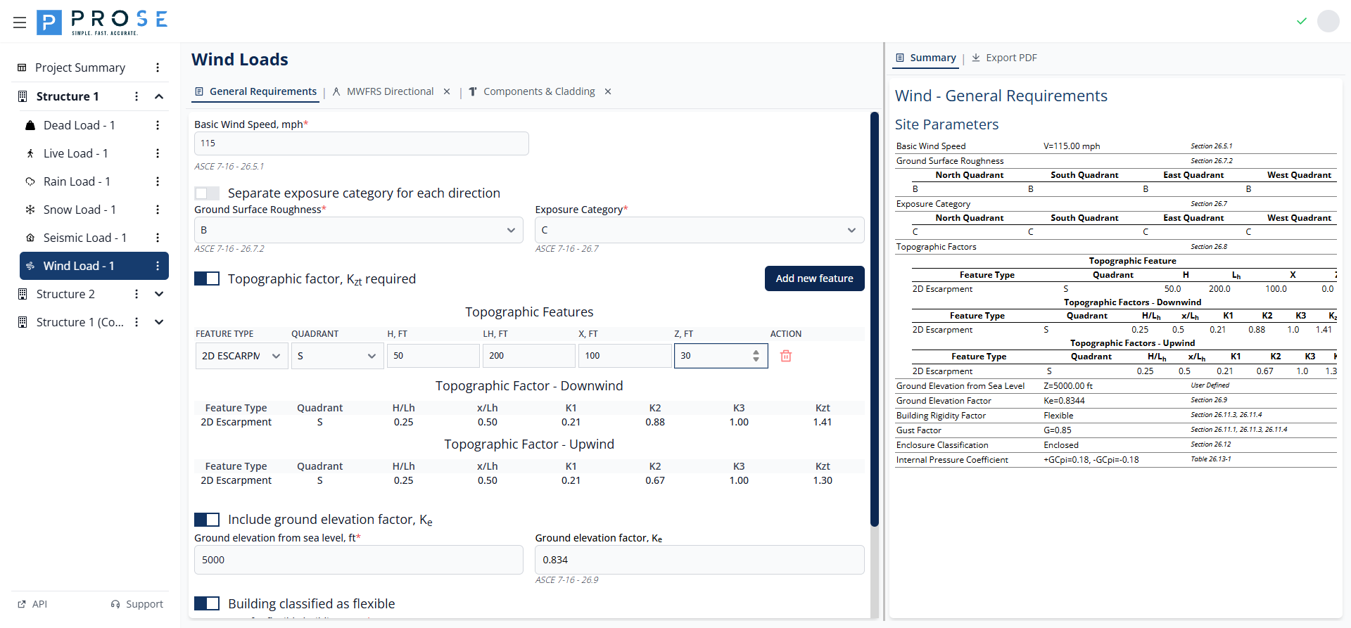
Topographic Feature Parameters
| Parameter | Description |
|---|---|
| Feature Type | 2D RIDGE, 2D ESCARPMENT, or 3D AXISYMMETRICAL HILL |
| Quadrant | Cardinal direction (N, E, S, W) where feature is located |
| H, ft | Height of the hill or escarpment relative to upwind terrain |
| Lh, ft | Distance upwind of crest to where the ground elevation is half H |
| x, ft | Distance from crest to building site (upwind is negative) |
| z, ft | Height above local ground level |
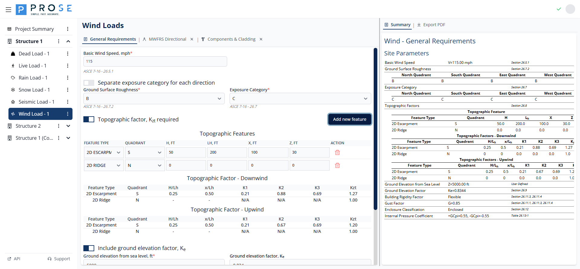
The module calculates K1, K2, K3 multipliers and the resulting Kzt factor for both upwind and downwind conditions. When H/Lh exceeds allowable limits or conditions don't warrant speed-up, Kzt defaults to 1.00.
Ground Elevation Factor
The ground elevation factor Ke accounts for reduced air density at high elevations per ASCE 7-16 Section 26.9.
- Check Include ground elevation factor, Ke to enable the calculation
- Enter the ground elevation from sea level in feet
- The Ke factor is calculated automatically

For sites at sea level, Ke = 1.000. Higher elevations result in lower Ke values, reducing wind pressures.
ASCE 7-10 vs ASCE 7-16
The ground elevation factor Ke was introduced in ASCE 7-16. When using ASCE 7-10, this option is not available as the standard assumes sea level air density.
Building Flexibility
Building flexibility affects the gust effect factor used in wind pressure calculations.
- Rigid Buildings: Use gust effect factor G = 0.85 (default)
- Flexible Buildings: Require calculation of gust effect factor Gf based on building dynamic properties

- Check Building classified as flexible if the building's fundamental natural frequency is less than 1 Hz
- Enter the calculated Gf value per ASCE 7-16 Sections 26.11.3 and 26.11.4
- Gf accounts for dynamic amplification from wind gusts
Enclosure Classification
Enclosure classification determines the internal pressure coefficient (GCpi) per ASCE 7-16 Section 26.13.
| Classification | GCpi | Application |
|---|---|---|
| ENCLOSED | ±0.18 | Buildings with no dominant openings |
| PARTIALLY ENCLOSED | ±0.55 | Buildings with dominant openings |
| OPEN | 0.00 | Buildings with 80%+ wall openings |
| PARTIALLY OPEN | Varies | Buildings between open and enclosed |
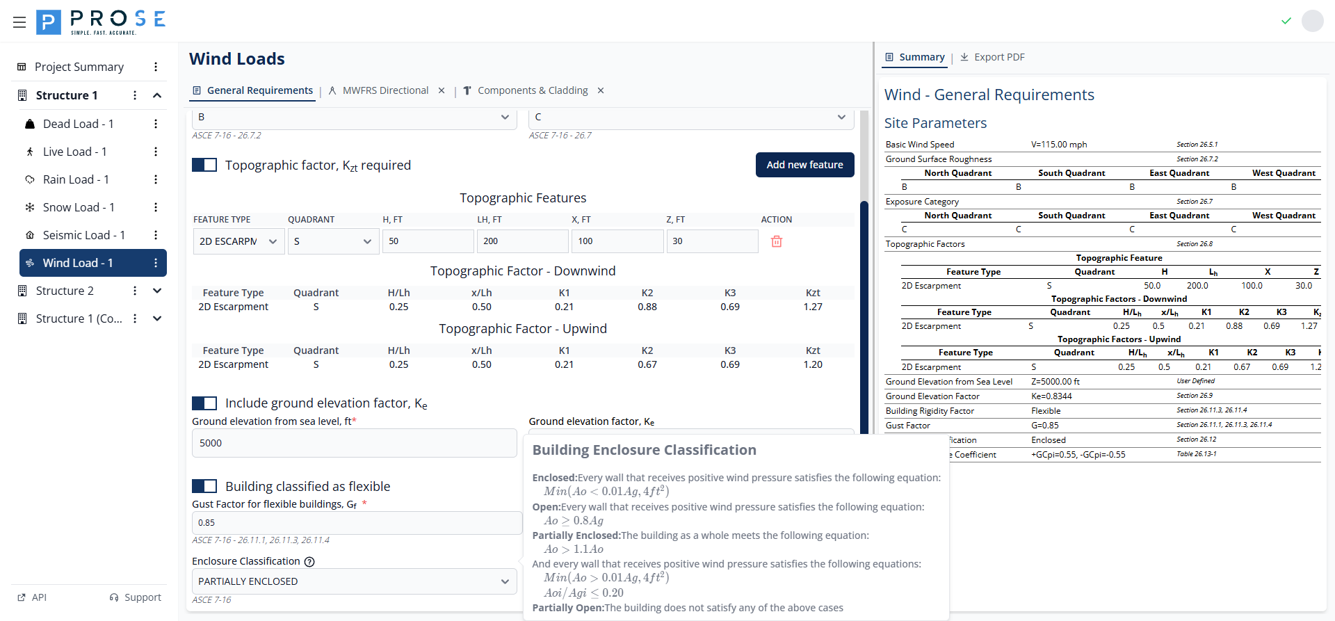
- Select the enclosure classification from the dropdown
- The Internal Pressure Coefficient (GCpi) updates automatically
- This value applies to all MWFRS and C&C calculations
Partially Enclosed Buildings
Partially enclosed buildings have significantly higher internal pressures (GCpi = ±0.55 vs ±0.18). Ensure accurate classification to avoid underestimating wind loads on building components.
MWFRS Directional Procedure
The MWFRS Directional tab implements Chapter 27 of ASCE 7 for calculating wind pressures on the Main Wind Force Resisting System. This method applies to buildings of all heights.
Opening the MWFRS Tab
The MWFRS Directional tab is a submodule that must be opened separately:
- Navigate to the Wind Load module
- Click the MWFRS Directional tab header
- The tab opens with default region configuration
To close the tab, click the X button on the tab header.
Wind Regions
Wind regions represent distinct building areas with independent wind pressure calculations. Each region has its own geometry, levels, and pressure calculations.
Adding Wind Regions
- Click the Add Region button at the top of the MWFRS panel
- A new region panel appears with default parameters
- Enter a descriptive name in the Region Description field
- Configure building information and design pressures
Region Description
Enter a meaningful name to identify each region (e.g., "Main Building", "Tower", "Podium"). This name appears in the summary and PDF export.
Building Information
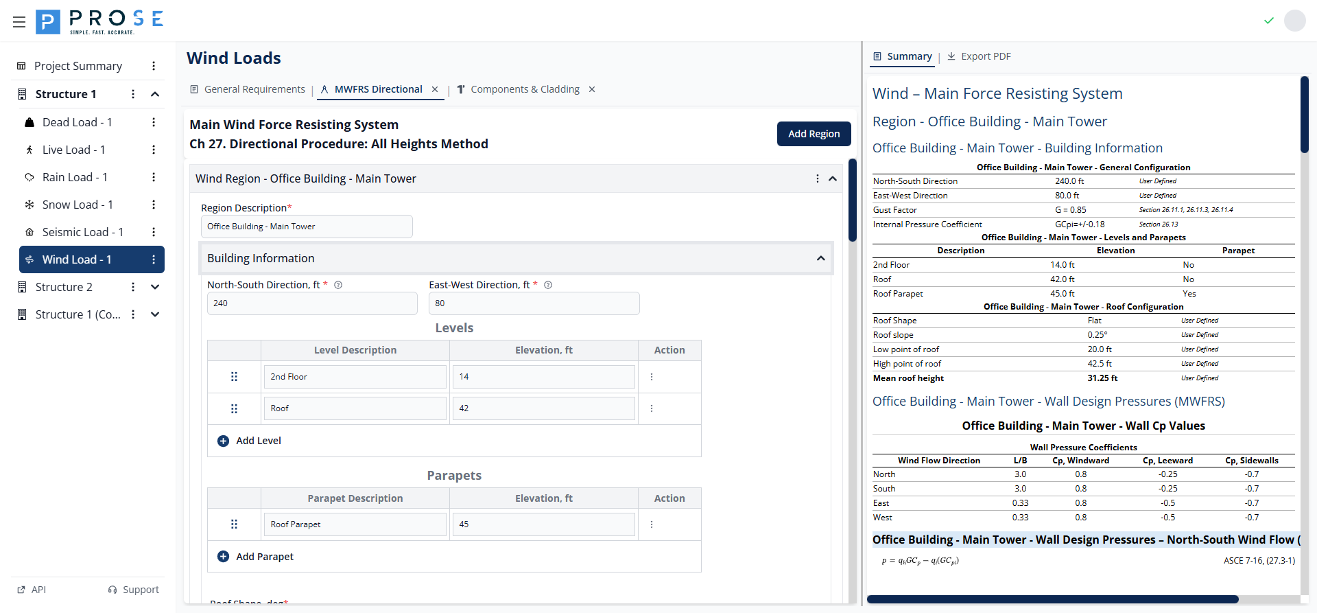
Building Dimensions
Configure the building plan dimensions for each region:
- North-South Direction, ft: Building dimension parallel to north-south axis
- East-West Direction, ft: Building dimension parallel to east-west axis
These dimensions determine the L/B ratio used for wall pressure coefficients.
Levels
Levels represent elevations where wall pressures are calculated. Each level has a description and elevation.
- Click Add Level to add a new level row
- Enter a description (e.g., "Roof", "Floor 2", "Ground")
- Enter the elevation in feet above grade
- Use the drag handle to reorder levels
- Click the delete button to remove a level
Parapets
Parapets are special levels that receive parapet-specific pressure calculations per Equation 27.3-4.
- Click Add Parapet to add a parapet row
- Enter a description (e.g., "High Parapet", "Low Parapet")
- Enter the top of parapet elevation in feet
- Parapet pressures include windward (+1.5 GCpn) and leeward (-1.0 GCpn) conditions
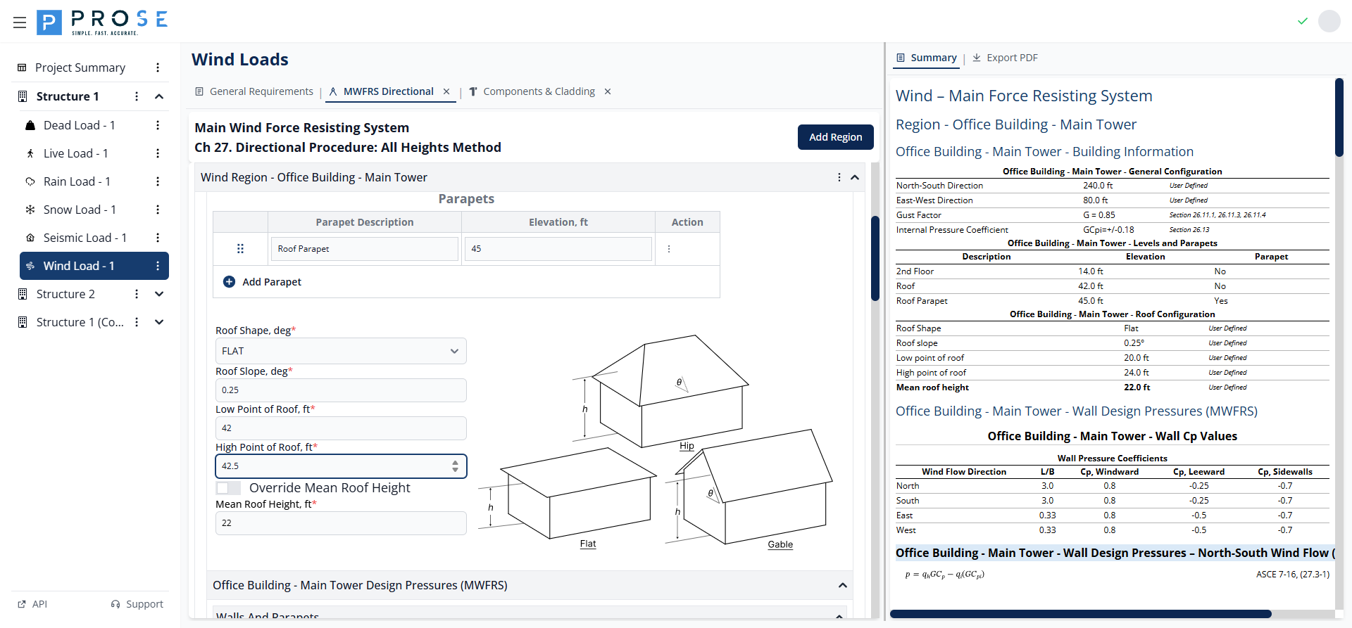
Roof Configuration
- Roof Shape: Select from OPEN MONOSLOPE, OPEN PITCHED, or OPEN TROUGHED
- Roof Slope, deg: Enter the roof slope angle (0° to 90°)
- Low Point of Roof, ft: Elevation of the lowest roof point
- High Point of Roof, ft: Elevation of the highest roof point
- Override Mean Roof Height: Check to manually specify mean roof height
- Mean Roof Height, ft: Calculated automatically or user-specified when overridden
A roof slope diagram displays the entered configuration for visual verification.
Design Pressures
The Design Pressures section calculates wind pressures for walls, parapets, and roof surfaces.
Wind Direction Tabs
Click the direction tabs (Wind - N, Wind - S, Wind - E, Wind - W) to view pressures for each wind direction. Calculations account for building orientation and dimension ratios.
Wall Pressures
Wall design pressures are calculated using Equation 27.3-1:
Where: - q = velocity pressure at elevation z (qz) or mean roof height (qh) - G = gust effect factor - Cp = external pressure coefficient - qi = velocity pressure for internal pressure - GCpi = internal pressure coefficient
Wall Pressure Coefficients display L/B ratio and Cp values for windward, leeward, and sidewall surfaces per Figure 27.3-1.
Case Types: - Case 1 (+GCpi): Maximum outward pressure on leeward/side walls - Case 2 (-GCpi): Maximum inward pressure on windward walls - Case Minimum: Code minimum pressures (16 psf walls, 8 psf roof)
Parapet Pressures
Parapet pressures are calculated using Equation 27.3-4:
The module calculates pressures for: - Windward parapet: GCpn = +1.5 - Leeward parapet: GCpn = -1.0
Roof Pressures
Roof pressures follow the same equation as walls with roof-specific Cp values from Section 27.3.2:
- Normal to Ridge: Windward and leeward Cp values
- Parallel to Ridge: Zone-based Cp values (0 to h/2, h/2 to h, h to 2h, > 2h)
MWFRS Summary
Click the Summary tab to view a comprehensive overview of all MWFRS calculations including: - Building configuration parameters - Levels and parapets table - Roof configuration - Wall Cp values for all directions - Wall design pressures (Case 1, Case 2, Case Minimum) for all directions - Parapet design pressures - Roof Cp values and design pressures
Components & Cladding
The Components & Cladding tab implements Chapter 30 of ASCE 7 for calculating wind pressures on building envelope components.
Opening the C&C Tab
- Navigate to the Wind Load module
- Click the Components & Cladding tab header
- The tab opens with default region configurations
C&C Region Types
The module supports three C&C region types, each with specific parameters and zone definitions:
- Walls ≤60ft: Wall pressures for buildings with mean roof height ≤ 60 ft
- Roofs: Roof pressures with zone-based GCp values
- Parapets: Parapet pressures combining wall and roof zones
Adding C&C Regions
- Click + Add C&C Region at the top of the panel
- Select the region type from the menu
- Configure region parameters
- Add effective areas for pressure calculations
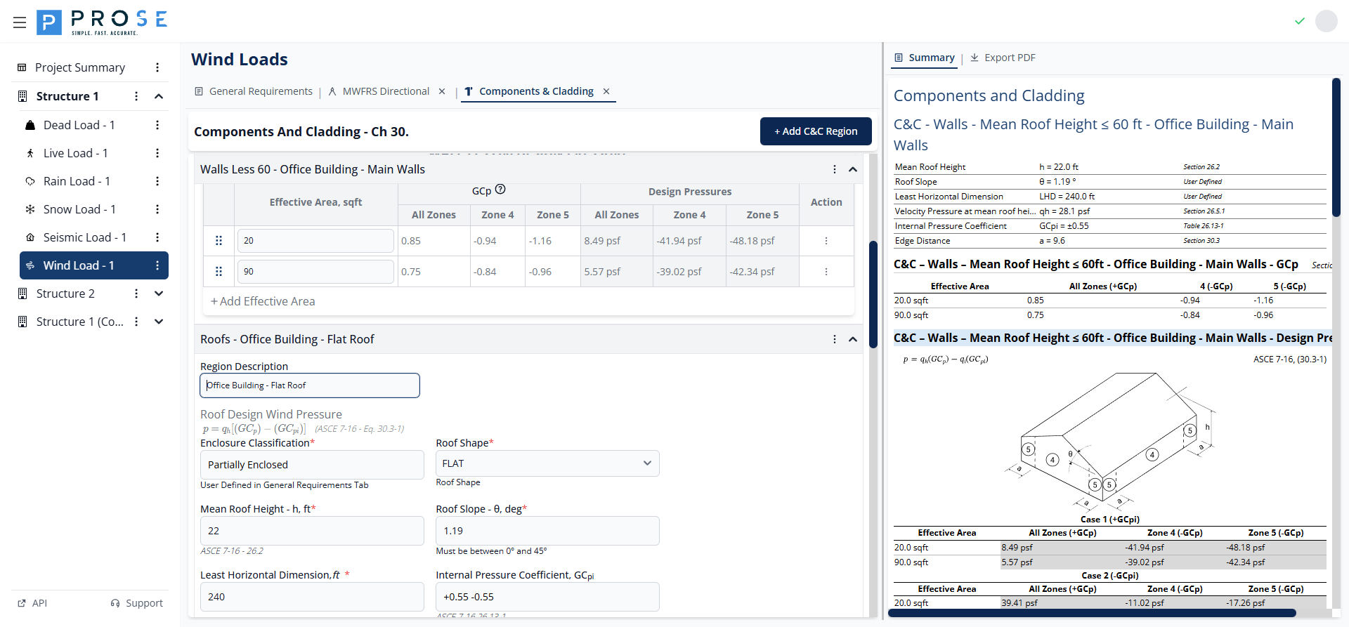
Walls Less Than 60 ft
For buildings with mean roof height not exceeding 60 ft, wall C&C pressures are calculated using simplified provisions.
Parameters
- Region Description: Descriptive name for the wall region
- Mean Roof Height, h: Building height (0-60 ft range)
- Roof Slope, θ: Roof angle in degrees (0-45° range)
- Least Horizontal Dimension: Smallest plan dimension
- Internal Pressure Coefficient, GCpi: From General Requirements
- Edge Region Distance, a: Calculated per Section 30.3
- Velocity Pressure, qh: Calculated at mean roof height
Wall Zones
Wall C&C pressures use zone definitions from Figure 30.3-1: - Zone 4: Interior wall zones - Zone 5: Corner wall zones (width = a)
Effective Areas
- Click Add Effective Area to add rows
- Enter the tributary area in square feet
- GCp values are interpolated based on effective area
- Design pressures calculate automatically for Case 1 and Case 2
Roofs
Roof C&C pressures account for multiple zones with varying pressure coefficients.
Parameters
- Region Description: Descriptive name for the roof region
- Enclosure Classification: Displays value from General Requirements
- Roof Shape: FLAT, GABLE, HIP, or MONOSLOPE
- Mean Roof Height, h: Building height
- Roof Slope, θ: Roof angle in degrees
- Least Horizontal Dimension: Smallest plan dimension
- Internal Pressure Coefficient, GCpi: From General Requirements
- Edge Region Distance, a: Calculated per Section 30.3
- Velocity Pressure, qh: Calculated at mean roof height
- Include Overhang: Check to include overhang pressures
Roof Zones
Roof C&C pressures use zone definitions from Figure 30.3-2: - Zone 1': Interior roof zone (low slope) - Zone 1: Interior roof zone - Zone 2: Edge zones - Zone 3: Corner zones
Effective Areas
- Click Add Effective Area to add rows
- Enter the tributary area in square feet
- GCp values display for all zones
- Design pressures show for Case 1 (+GCpi) and Case 2 (-GCpi)
Parapets
Parapet C&C pressures combine wall and roof zone pressures per Section 30.8.
Parameters
- Parapet Region Description: Descriptive name for the parapet
- Mean Roof Height, h: Building height
- Roof Shape: Select roof shape type
- Roof Slope, θ: Roof angle in degrees
- Structure Width, B: Building width perpendicular to parapet
Parapet Inputs
Each parapet row includes: - Top of Parapet Elevation: Height of parapet top - Effective Area: Tributary area in square feet - Walls Zone below Parapet: ZONE 4 or ZONE 5 - Roof Zone at Parapet: ZONE 1, ZONE 2, or ZONE 3 - Parapet Porosity: FULLY ENCLOSED, PARTIALLY ENCLOSED, OPEN, or PARTIALLY OPEN
Parapet Pressures
The module calculates four pressure cases: - P1: Positive pressure on windward face - P2: Negative pressure on windward face - P3: Positive pressure on leeward face - P4: Negative pressure on leeward face
C&C Summary
Click the Summary tab to view all C&C calculations including: - Wall region parameters and design pressures - Roof region parameters and zone pressures - Parapet configurations and combined pressures
Export to PDF
Generate professional documentation of your wind load calculations for project deliverables.
PDF Export Features
- Project Header: Project title, engineer, ID, and design code
- Company Branding: Logo and contact information
- General Wind Parameters: Basic wind speed, exposure, topographic factors
- MWFRS Results: Complete wall, parapet, and roof design pressures
- C&C Results: Zone-based design pressures for walls, roofs, and parapets
- ASCE 7 References: Equation numbers and section references
Generating PDFs
- Click the Export PDF tab on any Wind Load subtab
- The PDF generates automatically in the embedded viewer
- Review all sections and calculations
- Use viewer controls to zoom, navigate, or print
- Click Save in the PDF viewer toolbar to download
Best Practices
General Requirements Configuration
- Verify basic wind speed from ASCE 7 maps for your Risk Category
- Use separate exposure categories when site conditions vary significantly by direction
- Include topographic factors for buildings on or near hills, ridges, or escarpments
- Consider ground elevation factor for sites above 2,000 ft elevation
- Classify enclosure conservatively when openings are uncertain
MWFRS Analysis
- Create separate regions for building portions with different heights or geometries
- Include all significant levels for accurate pressure distribution
- Define parapets separately from wall levels for proper GCpn coefficients
- Verify roof configuration against architectural drawings
- Check Case Minimum pressures against calculated values
C&C Analysis
- Match effective areas to actual cladding element tributary areas
- Include all relevant zones where components are located
- Consider multiple effective areas for different cladding systems
- Verify parapet zone combinations match actual conditions
- Use Include Overhang option when applicable
Code Reference
The Wind Load module is based on ASCE 7-10 and ASCE 7-16 (Minimum Design Loads and Associated Criteria for Buildings and Other Structures):
ASCE 7-16 Primary References
- Section 26.5.1: Basic Wind Speed
- Section 26.7: Exposure Categories
- Section 26.7.2: Ground Surface Roughness
- Section 26.8.2: Topographic Factor Kzt
- Section 26.9: Ground Elevation Factor Ke
- Section 26.10: Velocity Pressure
- Section 26.11: Gust Effect Factor
- Section 26.13: Internal Pressure Coefficient
MWFRS References
- Chapter 27: Wind Loads - MWFRS Directional Procedure
- Equation 27.3-1: Wall and roof design pressure
- Equation 27.3-4: Parapet design pressure
- Figure 27.3-1: Wall pressure coefficients
- Section 27.3.2: Roof pressure coefficients
C&C References
- Chapter 30: Wind Loads - Components and Cladding
- Equation 30.3-1: C&C design pressure (h ≤ 60 ft)
- Equation 30.8-1: Parapet C&C design pressure
- Figure 30.3-1: Wall GCp values
- Figure 30.3-2: Roof GCp values
Code Variables
| Variable | Description | Units |
|---|---|---|
| V | Basic wind speed | mph |
| Kz | Velocity pressure exposure coefficient | - |
| Kzt | Topographic factor | - |
| Ke | Ground elevation factor | - |
| Kd | Wind directionality factor | - |
| G | Gust effect factor (rigid) | - |
| Gf | Gust effect factor (flexible) | - |
| qz | Velocity pressure at height z | psf |
| qh | Velocity pressure at mean roof height | psf |
| Cp | External pressure coefficient | - |
| GCpi | Internal pressure coefficient | - |
| GCp | Combined external pressure coefficient (C&C) | - |
| p | Design wind pressure | psf |
Typical Workflow
- Configure General Requirements: Set basic wind speed, exposure, and building parameters
- Add MWFRS Analysis: Create regions with building geometry and levels
- Review MWFRS Results: Check wall, parapet, and roof pressures for all directions
- Add C&C Analysis: Create regions for walls, roofs, and parapets with effective areas
- Review C&C Results: Verify zone pressures for cladding design
- Export Documentation: Download PDF for project records and permit submission