Components & Cladding
The Components & Cladding tab implements Chapter 30 of ASCE 7 for calculating wind pressures on building envelope components.
Key Features
- Multi-region support for walls, roofs, and parapets
- Automatic zone-based GCp calculations from effective areas
- Walls ≤60ft and Walls >60ft procedures per Sections 30.3 and 30.5
- Roof zones (1, 1', 2, 3) with shape-specific coefficients
- Parapet combined pressure calculations (P1-P4)
- Case 1 (+GCpi) and Case 2 (-GCpi) pressure tables
- Summary view with comprehensive pressure output
Getting Started
Prerequisites
Complete the General Requirements tab before configuring C&C pressures. Exposure category and enclosure classification directly affect zone pressures.
- Configure General Requirements (wind speed, exposure, enclosure)
- Click the Components & Cladding tab header
- Click + Add C&C Region to add a region
- Select the region type (Walls ≤60ft, Walls >60ft, Roofs, or Parapets)
- Configure region parameters (height, slope, dimensions)
- Add effective areas to calculate zone pressures
- Review Case 1 and Case 2 pressure tables
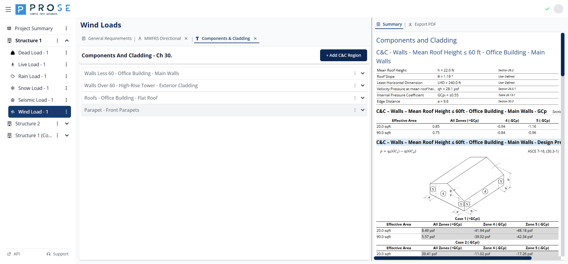
C&C Region Types
The module supports three C&C region types, each with specific parameters and zone definitions:
- Walls ≤60ft: Wall pressures for buildings with mean roof height ≤ 60 ft
- Roofs: Roof pressures with zone-based GCp values
- Parapets: Parapet pressures combining wall and roof zones
Adding C&C Regions
- Click + Add C&C Region at the top of the panel
- Select the region type from the menu
- Configure region parameters
- Add effective areas for pressure calculations
Walls Less Than 60 ft
For buildings with mean roof height not exceeding 60 ft, wall C&C pressures are calculated using simplified provisions per ASCE 7-16 Section 30.3.
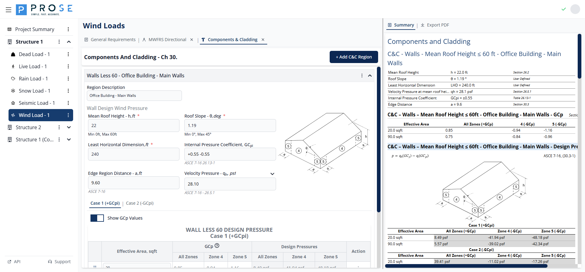
Parameters
- Region Description: Descriptive name for the wall region
- Mean Roof Height, h: Building height (0-60 ft range)
- Roof Slope, θ: Roof angle in degrees (0-45° range)
- Least Horizontal Dimension: Smallest plan dimension
- Internal Pressure Coefficient, GCpi: From General Requirements
- Edge Region Distance, a: Calculated per Section 30.3
- Velocity Pressure, qh: Calculated at mean roof height
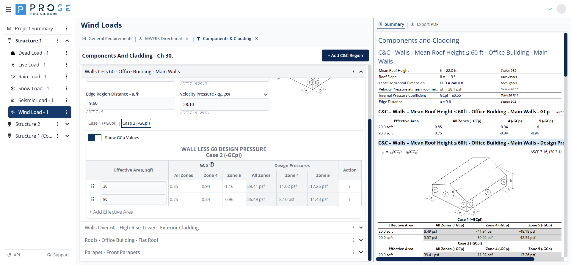
Wall Zones
Wall C&C pressures use zone definitions from Figure 30.3-1: - Zone 4: Interior wall zones - Zone 5: Corner wall zones (width = a)
Effective Areas
- Click Add Effective Area to add rows
- Enter the tributary area in square feet
- GCp values are interpolated based on effective area
- Design pressures calculate automatically for Case 1 and Case 2
Case 1 (+GCpi)
Case 1 applies positive internal pressure coefficient, resulting in maximum outward pressures on leeward and side walls.

Case 2 (-GCpi)
Case 2 applies negative internal pressure coefficient, resulting in maximum inward pressures on windward walls.
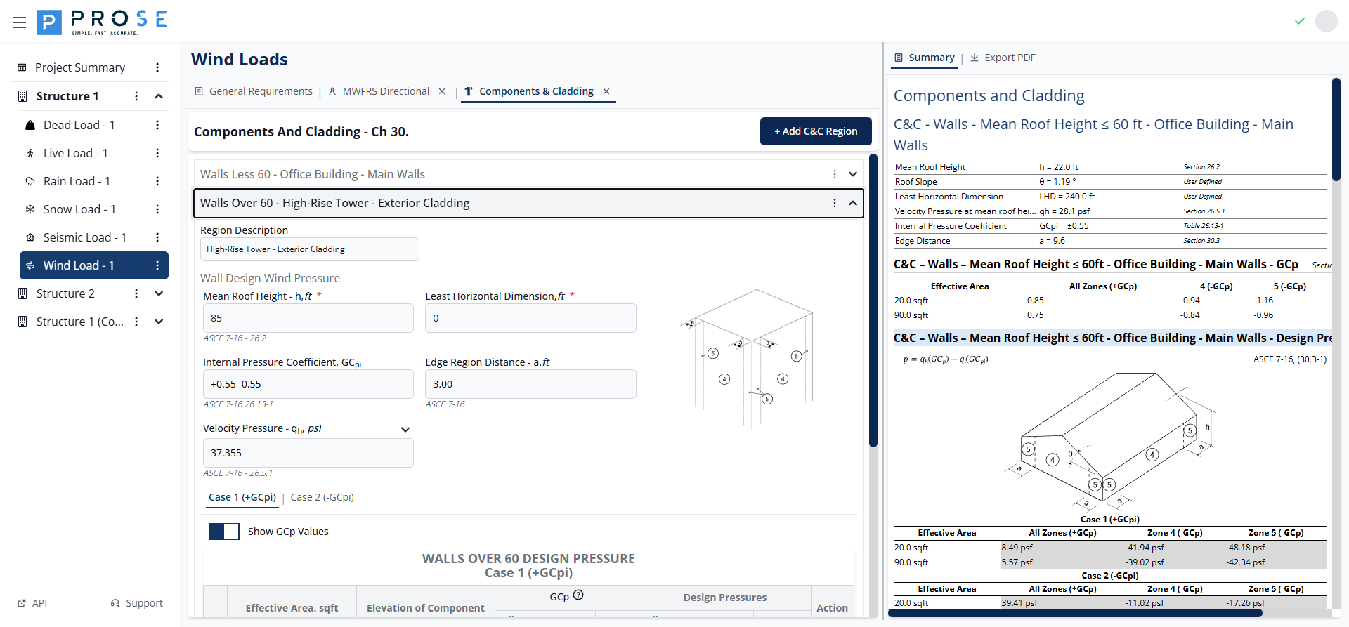
Walls Greater Than 60 ft
For buildings with mean roof height exceeding 60 ft, wall C&C pressures are calculated per ASCE 7-16 Section 30.5 with elevation-dependent velocity pressures.
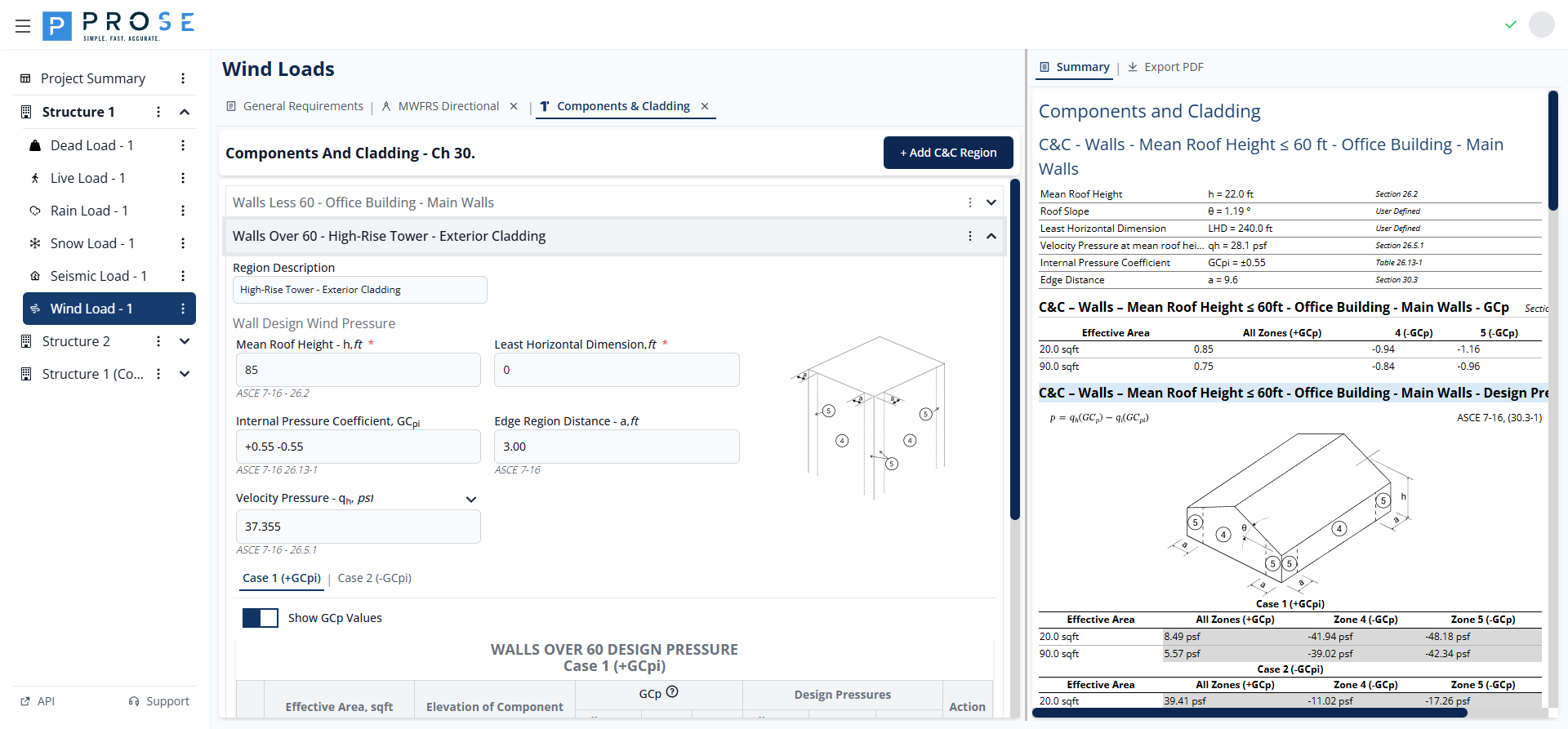
Wall Design Pressure Equation
Wall pressures are calculated using Equation 30.5-1:
Where: - q = velocity pressure at the elevation of the component - GCp = external pressure coefficient from Figure 30.5-1 - qi = velocity pressure for internal pressure (at mean roof height) - GCpi = internal pressure coefficient
Parameters
- Region Description: Descriptive name for the wall region
- Mean Roof Height, h: Building height (greater than 60 ft)
- Least Horizontal Dimension: Smallest plan dimension
- Internal Pressure Coefficient, GCpi: From General Requirements
- Edge Region Distance, a: Calculated per Section 30.3
- Velocity Pressure, qh: Calculated at mean roof height
Wall Zones
Wall C&C pressures for buildings over 60 ft use zone definitions from Figure 30.5-1: - Zone 4: Interior wall zones - Zone 5: Corner wall zones (width = a)
Effective Areas with Elevation
For walls greater than 60 ft, each effective area row includes: - Effective Area, sqft: Tributary area of the component - Elevation of Component: Height of component above grade - q: Velocity pressure at component elevation - qi: Velocity pressure for internal pressure
Case 1 (+GCpi)
Case 1 applies positive internal pressure coefficient for maximum outward pressures.
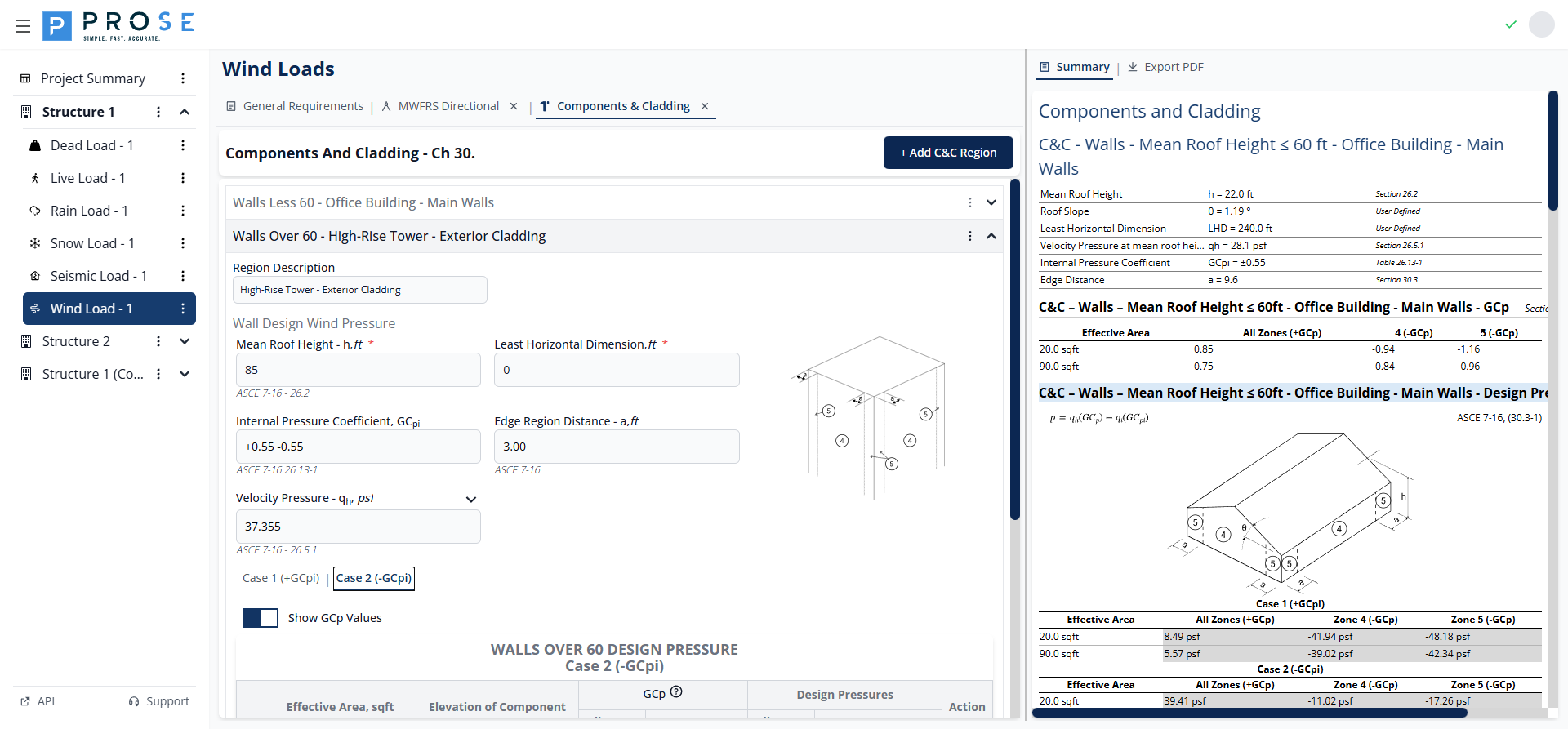
Case 2 (-GCpi)
Case 2 applies negative internal pressure coefficient for maximum inward pressures.
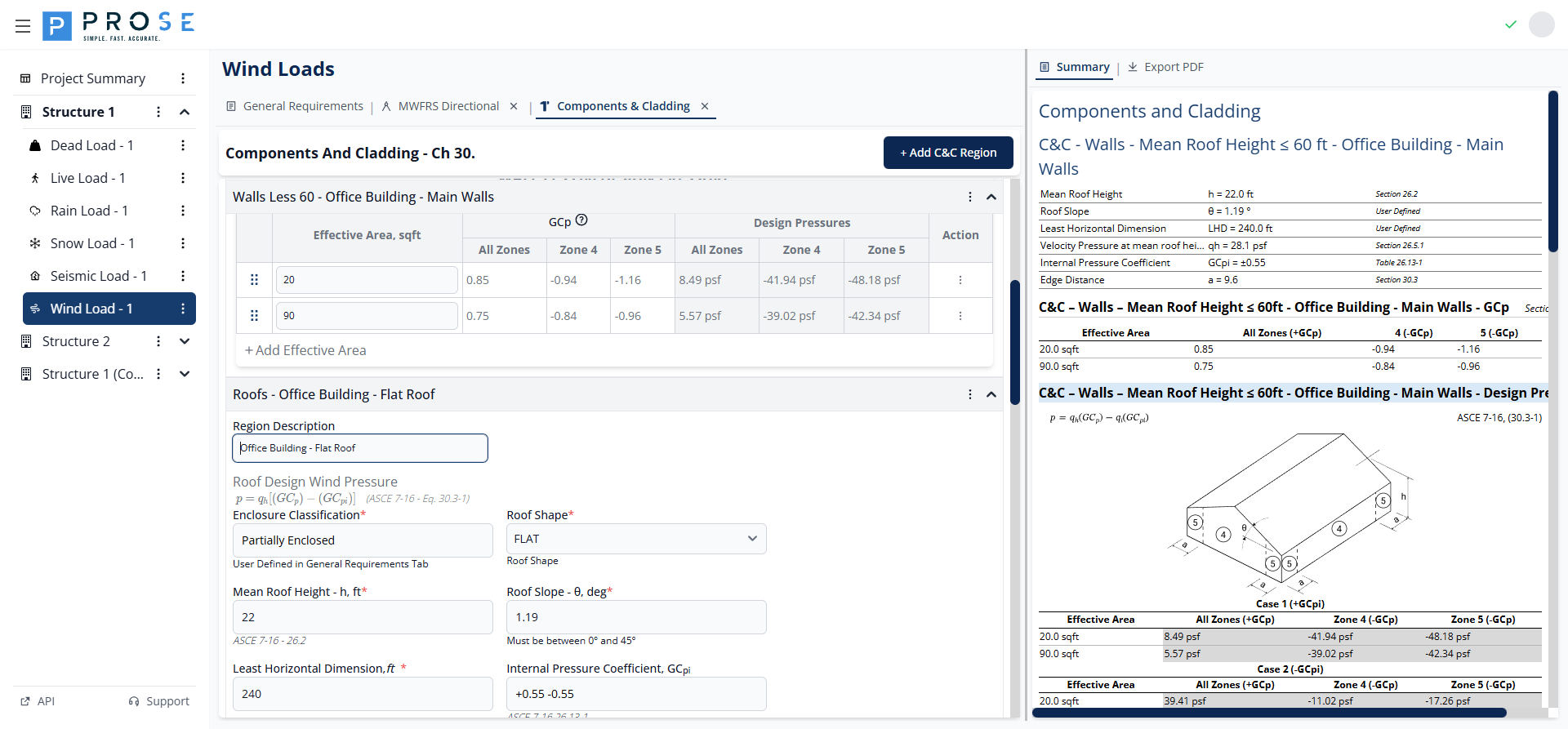
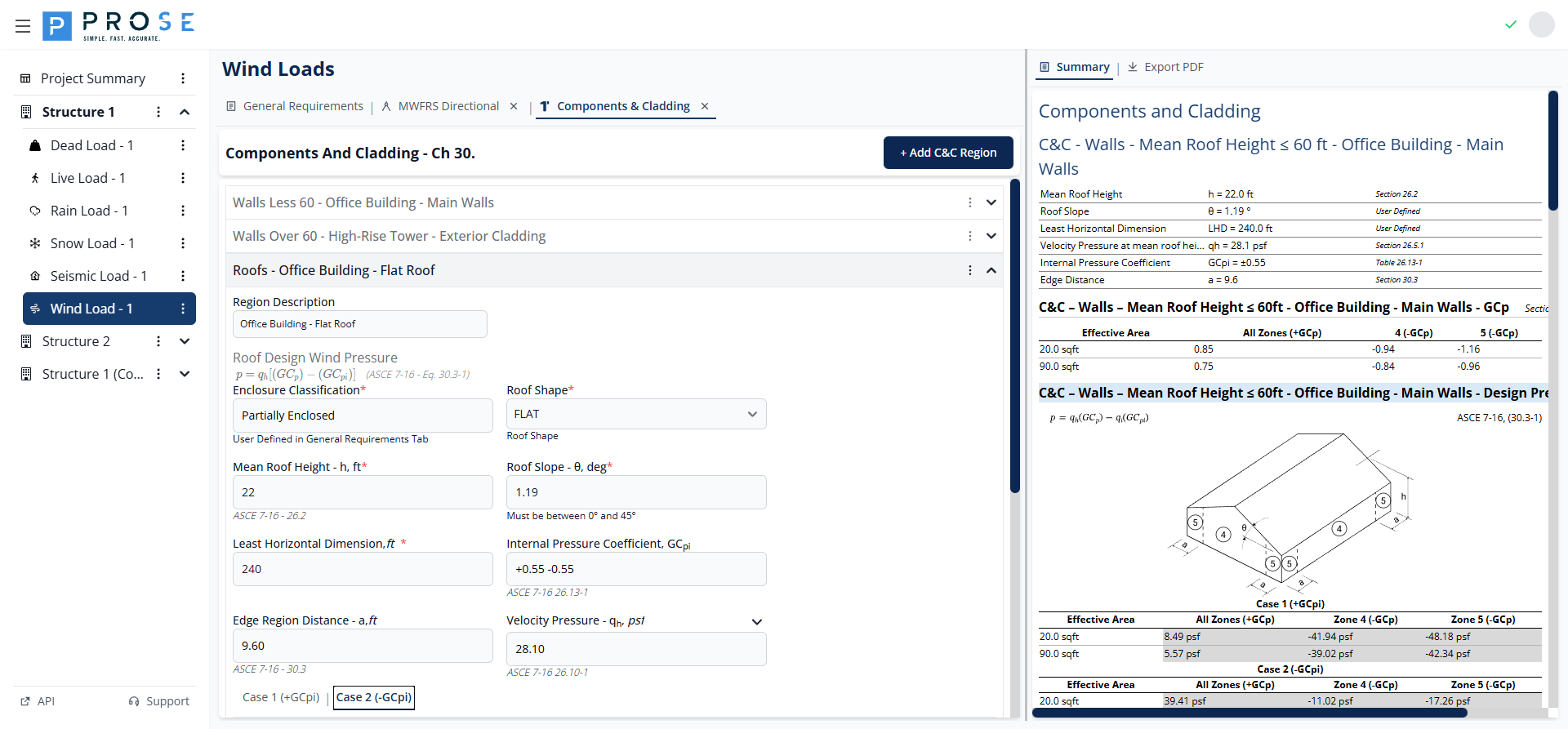
Roofs
Roof C&C pressures account for multiple zones with varying pressure coefficients per ASCE 7-16 Section 30.3.
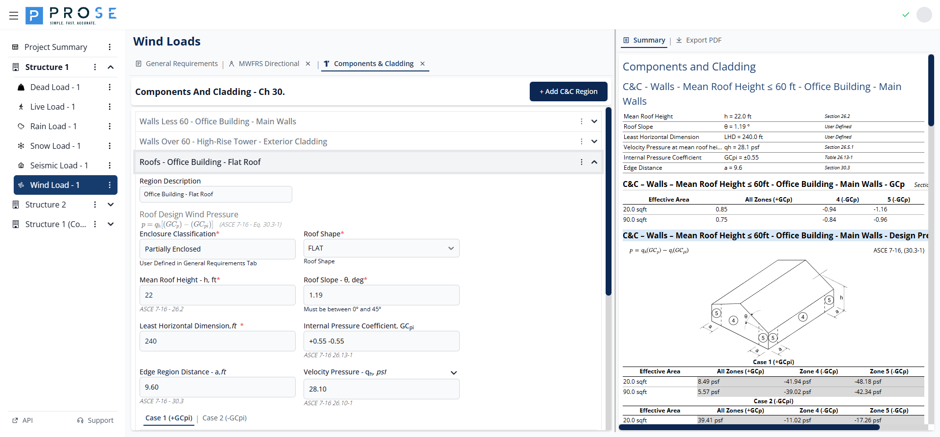
Roof Design Pressure Equation
Roof pressures are calculated using Equation 30.3-1:
Where: - qh = velocity pressure at mean roof height - GCp = external pressure coefficient from Figure 30.3-2 - GCpi = internal pressure coefficient
Parameters
- Region Description: Descriptive name for the roof region
- Enclosure Classification: Displays value from General Requirements
- Roof Shape: FLAT, GABLE, HIP, or MONOSLOPE
- Mean Roof Height, h: Building height
- Roof Slope, θ: Roof angle in degrees
- Least Horizontal Dimension: Smallest plan dimension
- Internal Pressure Coefficient, GCpi: From General Requirements
- Edge Region Distance, a: Calculated per Section 30.3
- Velocity Pressure, qh: Calculated at mean roof height
- Include Overhang: Check to include overhang pressures
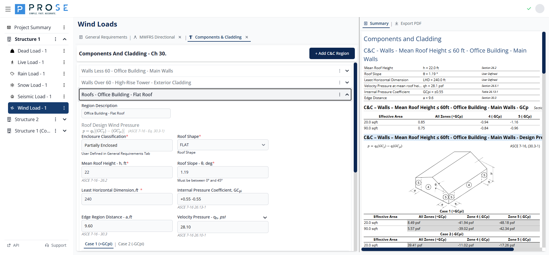
Roof Zones
Roof C&C pressures use zone definitions from Figure 30.3-2: - Zone 1': Interior roof zone (low slope, flat roofs only) - Zone 1: Interior roof zone - Zone 2: Edge zones (width = a from edge) - Zone 3: Corner zones (a × a at corners)
Effective Areas
- Click Add Effective Area to add rows
- Enter the tributary area in square feet
- GCp values display for all zones based on effective area
- Design pressures calculate for Case 1 (+GCpi) and Case 2 (-GCpi)
Case 1 (+GCpi)
Case 1 applies positive internal pressure coefficient, resulting in maximum uplift pressures.
Case 2 (-GCpi)
Case 2 applies negative internal pressure coefficient, reducing net uplift pressures.
Parapets
Parapet C&C pressures combine wall and roof zone pressures per ASCE 7-16 Section 30.8.
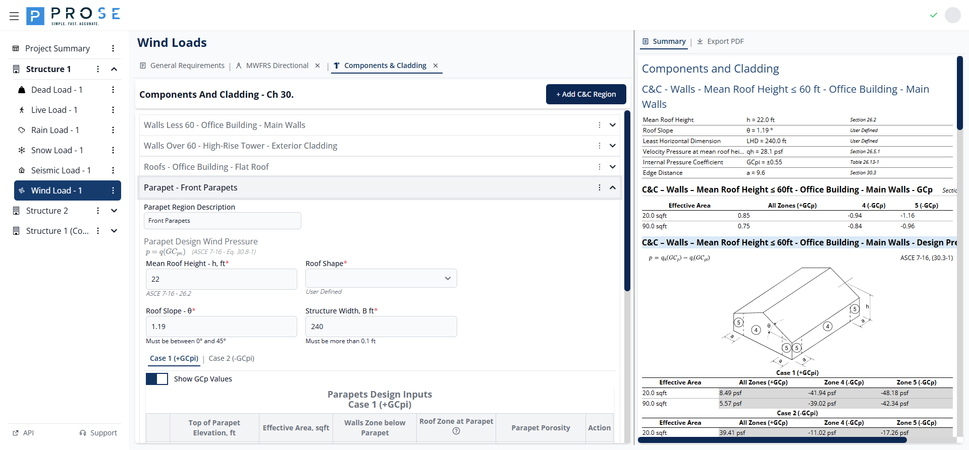
Parapet Design Pressure Equation
Parapet pressures are calculated using Equation 30.8-1:
Where: - q = velocity pressure at top of parapet - GCpn = combined net pressure coefficient
Parameters
- Parapet Region Description: Descriptive name for the parapet
- Mean Roof Height, h: Building height
- Roof Shape: Select roof shape type
- Roof Slope, θ: Roof angle in degrees
- Structure Width, B: Building width perpendicular to parapet
Parapet Inputs
Each parapet row includes: - Top of Parapet Elevation: Height of parapet top - Effective Area: Tributary area in square feet - Walls Zone below Parapet: ZONE 4 or ZONE 5 - Roof Zone at Parapet: ZONE 1, ZONE 2, or ZONE 3 - Parapet Porosity: FULLY ENCLOSED, PARTIALLY ENCLOSED, OPEN, or PARTIALLY OPEN
Parapet Pressures
The module calculates four pressure cases combining wall and roof GCp values: - P1: Positive pressure on windward face (wall +GCp combined with roof -GCp) - P2: Negative pressure on windward face (wall -GCp combined with roof -GCp) - P3: Positive pressure on leeward face (wall +GCp combined with roof +GCp) - P4: Negative pressure on leeward face (wall -GCp combined with roof +GCp)
Case 1 (+GCpi)
Case 1 applies positive internal pressure coefficient to parapet pressures.

Case 2 (-GCpi)
Case 2 applies negative internal pressure coefficient to parapet pressures.

C&C Summary
Click the Summary tab to view all C&C calculations. The summary provides a comprehensive report including:
- Wall Regions: Parameters, GCp values, and design pressures for both Case 1 and Case 2
- Roof Regions: Parameters, zone-based GCp values, and design pressures for all zones
- Parapet Regions: Configurations, combined GCp values, and P1-P4 design pressures
- Code References: ASCE 7-16 equation and section references for each calculation
The summary displays: - Region parameters with code references - GCp coefficient tables by effective area and zone - Design pressure tables for Case 1 (+GCpi) and Case 2 (-GCpi) - Notes on sign conventions and minimum pressure requirements
Best Practices
Region Organization
- Create separate regions for distinct cladding conditions
- Use the appropriate wall procedure based on mean roof height (≤60ft vs >60ft)
- Model different roof areas separately when shapes or slopes vary
Effective Area Selection
- Use actual tributary areas for cladding components and fasteners
- Include multiple effective areas to cover range of cladding elements
- Consider both large panels and small fasteners in your analysis
Zone Considerations
- Identify corner and edge zones on architectural drawings
- Apply Zone 2 and Zone 3 coefficients to edge and corner cladding
- Document zone widths (dimension "a") for cladding specifications
Parapet Design
- Configure parapet pressures using appropriate wall and roof zone combinations
- Consider all four pressure cases (P1-P4) for parapet coping design
- Account for parapet porosity effects on pressure calculations
Code Reference
Components and cladding per ASCE 7-16:
- Chapter 30: Wind Loads on C&C
- Section 30.3: Low-Rise Buildings (h ≤ 60 ft)
- Section 30.5: Buildings with h > 60 ft
- Section 30.8: Parapets
- Figure 30.3-1: Wall Zones and GCp Values (h ≤ 60 ft)
- Figure 30.3-2: Roof Zones and GCp Values
- Figure 30.5-1: Wall Zones and GCp Values (h > 60 ft)
- Equation 30.3-1: C&C Design Pressure (Low-Rise)
- Equation 30.5-1: C&C Design Pressure (All Heights)
- Equation 30.8-1: Parapet Design Pressure