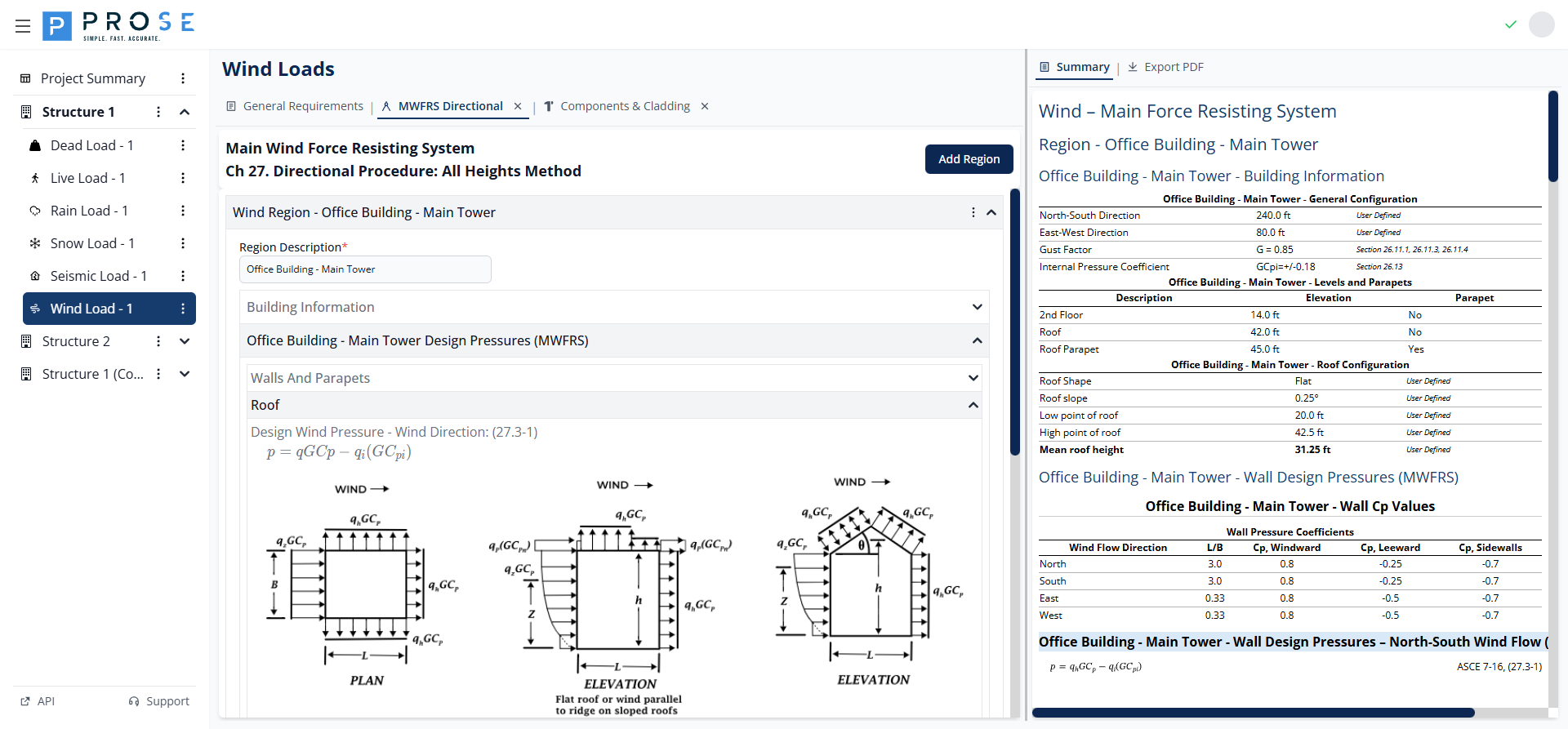
MWFRS Directional Procedure
The MWFRS Directional tab implements Chapter 27 of ASCE 7 for calculating wind pressures on the Main Wind Force Resisting System. This method applies to buildings of all heights.
Key Features
- Multi-region support for complex building configurations
- Four cardinal wind direction analysis (N, S, E, W)
- Automatic wall pressure coefficient (Cp) calculation from L/B ratios
- Multi-level wall pressure tables with velocity pressure profile
- Parapet wind pressure calculations per Equation 27.3-4
- Roof pressure zones for various roof configurations
- Case 1, Case 2, and Code Minimum pressure calculations
- Summary view with comprehensive pressure tables
Getting Started
Prerequisites
Complete the General Requirements tab before configuring MWFRS pressures. Wind speed, exposure, and enclosure settings affect all pressure calculations.
- Configure General Requirements (wind speed, exposure, enclosure)
- Click the MWFRS Directional tab header
- Click Add Region to create a building region
- Enter building dimensions and levels
- Configure roof shape and slope
- Review design pressures for each wind direction
- Check Summary tab for all calculations
Wind Region Management
Wind regions represent distinct building areas with independent wind pressure calculations.
Adding Wind Regions
- Click the Add Region button at the top of the MWFRS panel
- A new region panel appears with default parameters
- Enter a descriptive name in the Region Description field
- Configure building information and design pressures
Editing Wind Regions
- Click on the region header to expand the panel
- Modify the Region Description, dimensions, or levels as needed
- Changes are saved automatically
- Use the tabs to switch between wind directions
Deleting Wind Regions
- Expand the region panel
- Click the Delete Region button
- Confirm the deletion when prompted
Cascading Deletion
Deleting a wind region removes all its levels, parapets, and pressure calculations.
Region Description
Enter a meaningful name to identify each region (e.g., "Main Building", "Tower", "Podium"). This name appears in the summary and PDF export.
Building Information
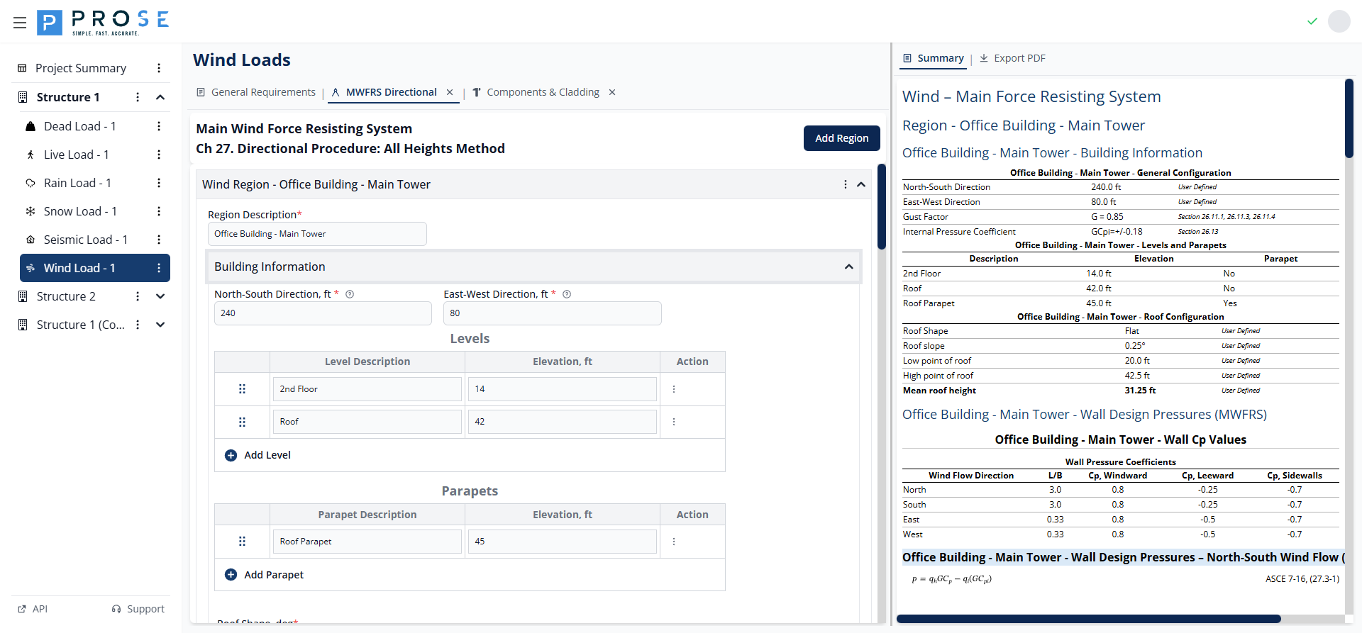
Building Dimensions
Configure the building plan dimensions for each region:
- North-South Direction, ft: Building dimension parallel to north-south axis
- East-West Direction, ft: Building dimension parallel to east-west axis
These dimensions determine the L/B ratio used for wall pressure coefficients.
Levels
Levels represent elevations where wall pressures are calculated. Each level has a description and elevation.
- Click Add Level to add a new level row
- Enter a description (e.g., "Roof", "Floor 2", "Ground")
- Enter the elevation in feet above grade
- Use the drag handle to reorder levels
- Click the delete button to remove a level
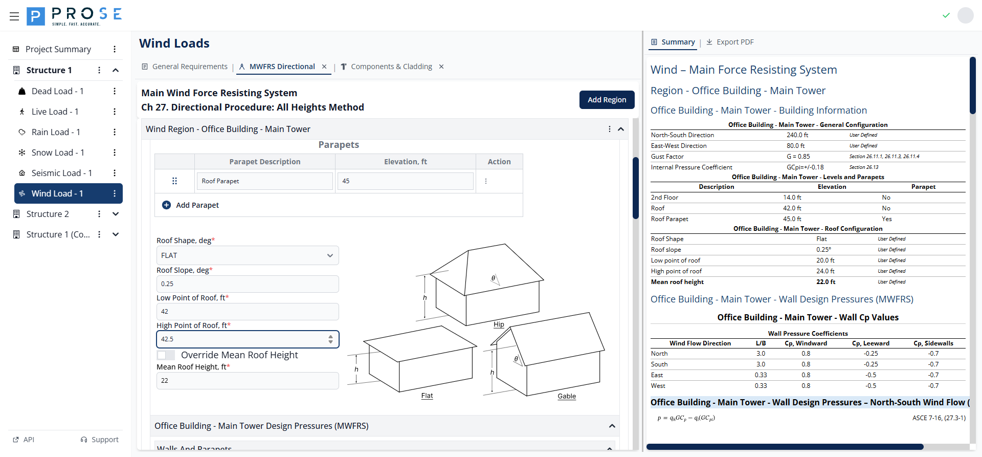
Parapets
Parapets are special levels that receive parapet-specific pressure calculations per Equation 27.3-4.
- Click Add Parapet to add a parapet row
- Enter a description (e.g., "High Parapet", "Low Parapet")
- Enter the top of parapet elevation in feet
- Parapet pressures include windward (+1.5 GCpn) and leeward (-1.0 GCpn) conditions
Roof Configuration
- Roof Shape: Select from OPEN MONOSLOPE, OPEN PITCHED, or OPEN TROUGHED
- Roof Slope, deg: Enter the roof slope angle (0° to 90°)
- Low Point of Roof, ft: Elevation of the lowest roof point
- High Point of Roof, ft: Elevation of the highest roof point
- Override Mean Roof Height: Check to manually specify mean roof height
- Mean Roof Height, ft: Calculated automatically or user-specified when overridden
A roof slope diagram displays the entered configuration for visual verification.
Design Pressures
The Design Pressures section calculates wind pressures for walls, parapets, and roof surfaces.
Wind Direction Tabs
Click the direction tabs (Wind - N, Wind - S, Wind - E, Wind - W) to view pressures for each wind direction. Calculations account for building orientation and dimension ratios.
Wall Pressures
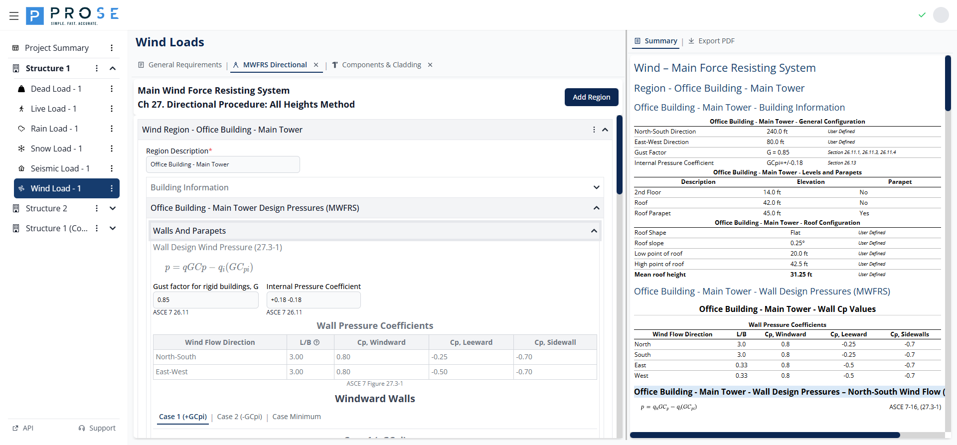
Wall design pressures are calculated using Equation 27.3-1:
Where: - q = velocity pressure at elevation z (qz) or mean roof height (qh) - G = gust effect factor - Cp = external pressure coefficient - qi = velocity pressure for internal pressure - GCpi = internal pressure coefficient
Wall Pressure Coefficients display L/B ratio and Cp values for windward, leeward, and sidewall surfaces per Figure 27.3-1.
Case Types: - Case 1 (+GCpi): Maximum outward pressure on leeward/side walls - Case 2 (-GCpi): Maximum inward pressure on windward walls - Case Minimum: Code minimum pressures (16 psf walls, 8 psf roof)
Parapet Pressures
Parapet pressures are calculated using Equation 27.3-4:
The module calculates pressures for: - Windward parapet: GCpn = +1.5 - Leeward parapet: GCpn = -1.0
Roof Pressures
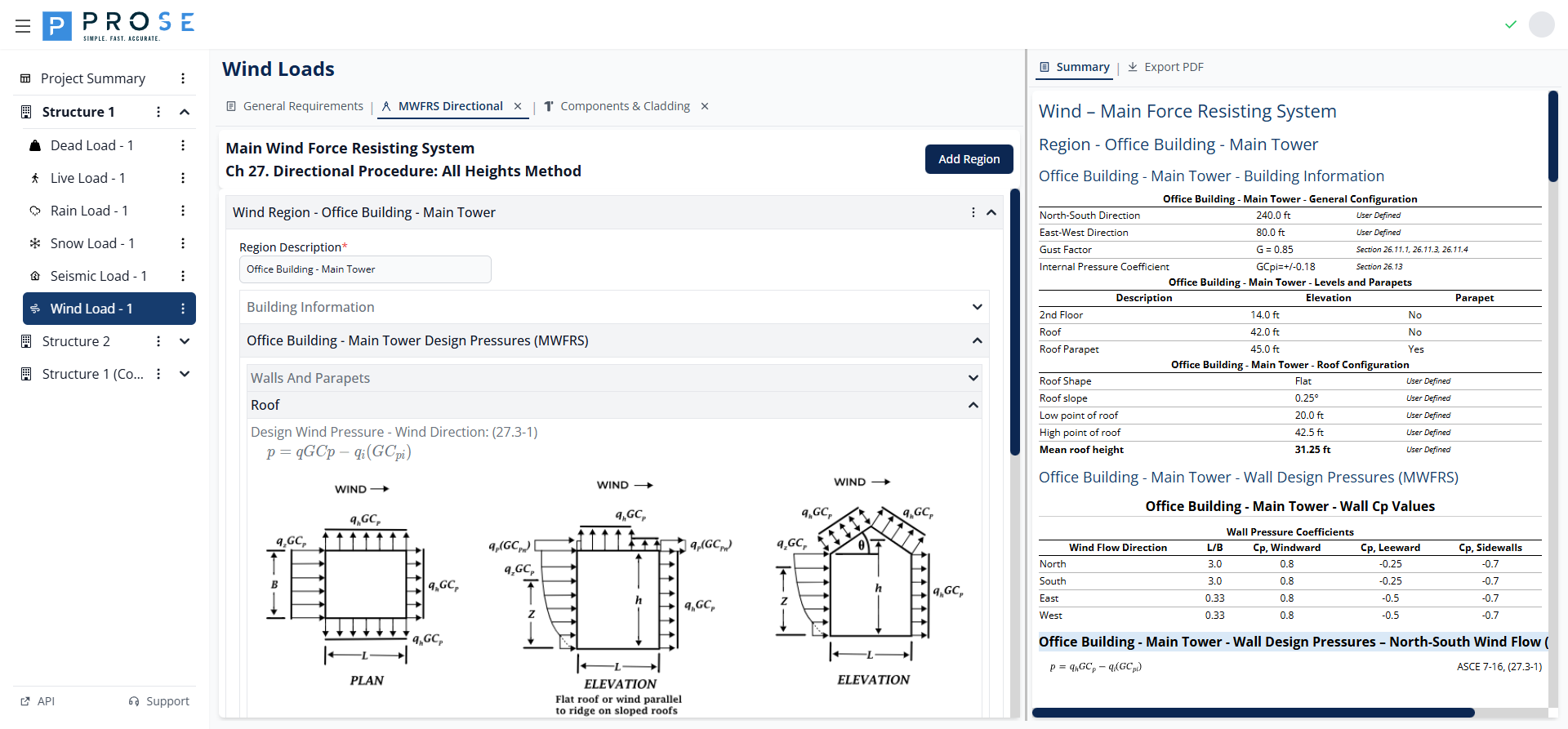
Roof pressures follow the same equation as walls with roof-specific Cp values from Section 27.3.2:
- Normal to Ridge: Windward and leeward Cp values
- Parallel to Ridge: Zone-based Cp values (0 to h/2, h/2 to h, h to 2h, > 2h)
MWFRS Summary
Click the Summary tab to view a comprehensive overview of all MWFRS calculations including: - Building configuration parameters - Levels and parapets table - Roof configuration - Wall Cp values for all directions - Wall design pressures (Case 1, Case 2, Case Minimum) for all directions - Parapet design pressures - Roof Cp values and design pressures
Best Practices
Region Organization
- Create separate regions for distinct building masses or heights
- Use descriptive region names that match architectural drawings
- Model podiums, towers, and appendages as separate regions
Level Configuration
- Include all significant floor levels for complete pressure distribution
- Add parapets as separate entries for accurate parapet pressure calculations
- Verify mean roof height calculation matches design intent
Pressure Cases
- Consider both Case 1 (+GCpi) and Case 2 (-GCpi) for all components
- Check that minimum pressures (16 psf walls, 8 psf roof) don't govern
- Apply internal pressure cases consistently across all surfaces
Roof Configuration
- Select roof shape that best matches actual geometry
- Verify roof slope input produces expected Cp values
- Model complex roofs with multiple regions if needed
Code Reference
MWFRS directional procedure per ASCE 7-16:
- Chapter 27: Wind Loads on MWFRS - Directional Procedure
- Section 27.1: Scope and Application
- Section 27.3: Design Wind Loads - Regular Shaped Buildings
- Equation 27.3-1: Wall and Roof Design Pressure
- Equation 27.3-4: Parapet Design Pressure
- Figure 27.3-1: Wall Pressure Coefficients (Cp)
- Section 27.3.2: Roof Pressure Coefficients
- Section 27.4: Design Wind Loads - All Heights (Part 2)